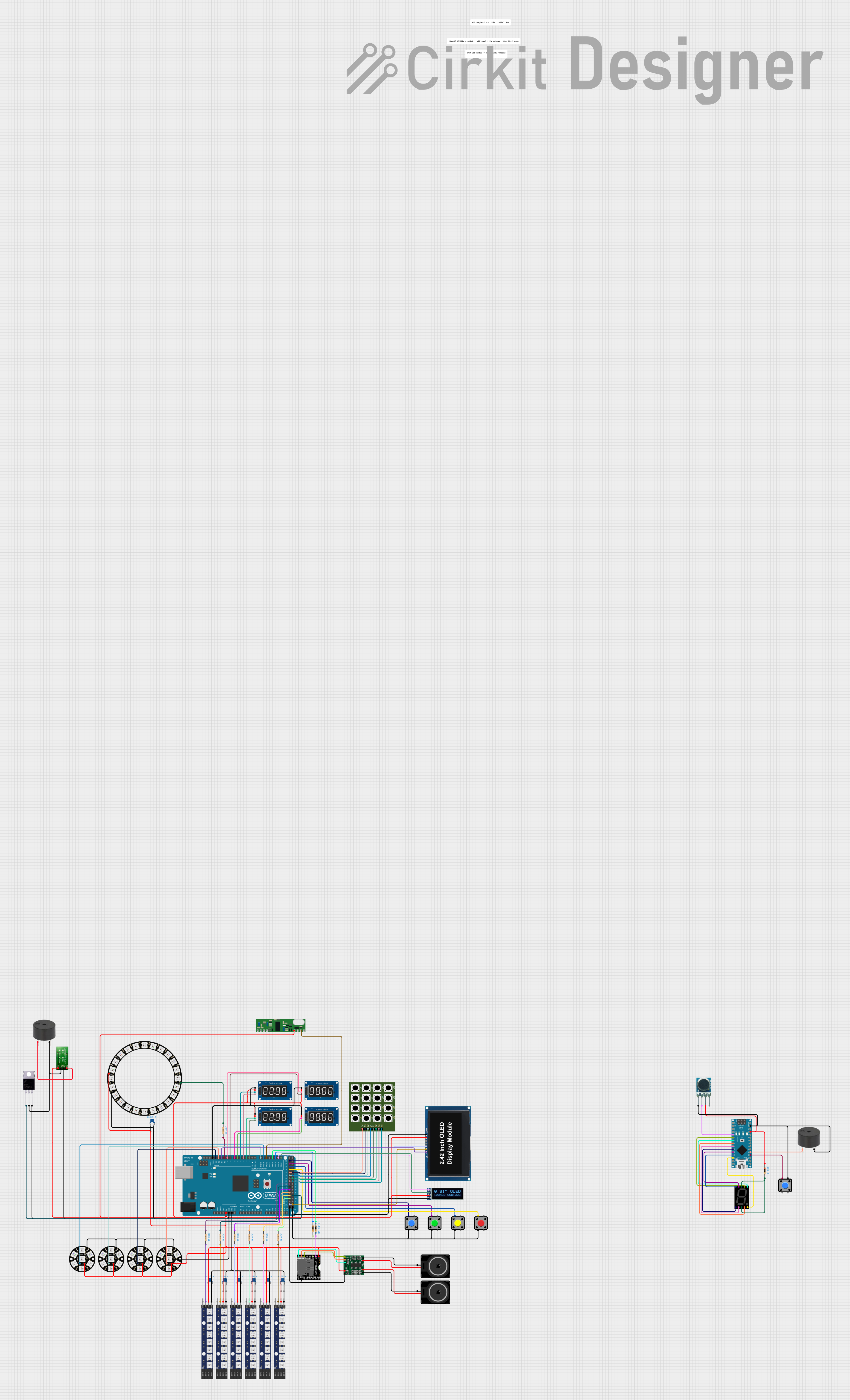
Arduino Mega-Nano Hybrid Control Panel with Wireless Communication and LED Displays

Circuit Documentation
Summary
The circuit in question appears to be a complex system involving user input devices, a microcontroller, RF communication modules, audio output, and LED displays. The primary controller is an Arduino Mega 2560, which interfaces with a variety of components including pushbuttons, a 4x4 keypad, an OLED display, LED matrices, a buzzer, an RF transmitter and receiver, a sound module (DFPlayer MINI), an amplifier (PAM8403), and several TM1637-based 7-segment display drivers. There is also an Arduino Nano that controls a seven-segment display and a buzzer. The circuit likely serves a multifunctional purpose, possibly for a user interface panel with visual feedback and RF communication capabilities.
Component List
Input Devices
- Pushbuttons: Used for user input, likely to trigger or control certain actions in the circuit.
- 4x4 Keypad: Provides additional user input options with multiple keys.
Microcontrollers
- Arduino Mega 2560: Acts as the central processing unit, controlling various peripherals and handling logic.
- Arduino Nano: A smaller microcontroller for dedicated tasks or as a secondary controller.
Communication Modules
- 433MHz RF Transmitter: Allows wireless data transmission.
- RXN433MHz Receiver: Receives data transmitted by the RF transmitter.
Audio Components
- DFPlayer MINI: A small sound module capable of playing back audio files from a microSD card.
- PAM8403: An audio amplifier for driving speakers.
- Loudspeakers: Output devices for audio playback.
- Buzzers: Provide audible alerts or feedback.
Display Components
- OLED Display 2.42": A graphical display for visual output.
- OLED Display 128x32: A smaller graphical display for text or simple graphics.
- TM1637 7-Segment Displays: Used to display numerical data.
- Seven Segment Display (Wokwi Compatible): Another numerical display controlled by the Arduino Nano.
- WS2812 RGB LED Matrices: Addressable LED arrays for colorful visual feedback.
- Adafruit NeoPixel Rings and Jewels: Individually addressable RGB LEDs for custom lighting effects.
Power Management
- 5V to 12V Step-up Converter: Boosts voltage to power components requiring 12V from a 5V source.
Miscellaneous
- Resistors: Various resistors used for current limiting and voltage division.
- Ceramic Capacitors: Likely used for decoupling and noise suppression.
- Mosfet: A transistor used for switching or amplifying electronic signals.
Wiring Details
Input Devices
- Pushbuttons: Connected to various digital pins on the Arduino Mega 2560 for input detection. Grounded on one side.
- 4x4 Keypad: Rows and columns connected to digital pins on the Arduino Mega 2560 for keypress detection.
Microcontrollers
- Arduino Mega 2560: Wired to various components for control and data exchange. Ground and power pins are connected to common rails.
- Arduino Nano: Controls a seven-segment display and a buzzer. Also interfaces with the RF transmitter.
Communication Modules
- 433MHz RF Transmitter: Data input connected to a digital pin on the Arduino Nano. Powered by the 5V output from the Nano.
- RXN433MHz Receiver: Data output connected to a digital pin on the Arduino Mega 2560.
Audio Components
- DFPlayer MINI: Speaker outputs connected to the PAM8403 amplifier. Serial communication lines connected to the Arduino Mega 2560 through resistors.
- PAM8403: Inputs connected to the DFPlayer MINI. Outputs connected to loudspeakers.
- Loudspeakers: Wired to the amplifier outputs.
- Buzzers: One buzzer connected to the Arduino Nano, another to a step-up converter and controlled via a Mosfet.
Display Components
- OLED Displays: Communicate with the Arduino Mega 2560 via I2C (SCL and SDA) and control lines.
- TM1637 7-Segment Displays: CLK and DIO lines connected to digital pins on the Arduino Mega 2560.
- Seven Segment Display (Wokwi Compatible): Segments controlled by digital pins on the Arduino Nano.
- WS2812 RGB LED Matrices: Data In pins chained and connected to digital pins on the Arduino Mega 2560 through resistors.
- Adafruit NeoPixel Rings and Jewels: Data In pins connected to digital pins on the Arduino Mega 2560.
Power Management
- 5V to 12V Step-up Converter: Input connected to the 5V rail, output provides 12V to the buzzer through a Mosfet.
Miscellaneous
- Resistors: Used in various parts of the circuit for current limiting and pull-up/pull-down resistors.
- Ceramic Capacitors: Likely placed near power supply pins of ICs for decoupling.
- Mosfet: Controls the power to the buzzer from the step-up converter.
Documented Code
Arduino Mega 2560 Code (sketch.ino)
void setup() {
  // put your setup code here, to run once:

}

void loop() {
  // put your main code here, to run repeatedly:

}
Arduino Nano Code (sketch.ino)
void setup() {
  // put your setup code here, to run once:

}

void loop() {
  // put your main code here, to run repeatedly:

}
Note: The provided code for both microcontrollers is a template with empty setup and loop functions. Actual functionality needs to be implemented according to the circuit's requirements.