
Arduino Nano-Based Automated Greenhouse Control System with LCD Display
View and Edit Project In Cirkit Designer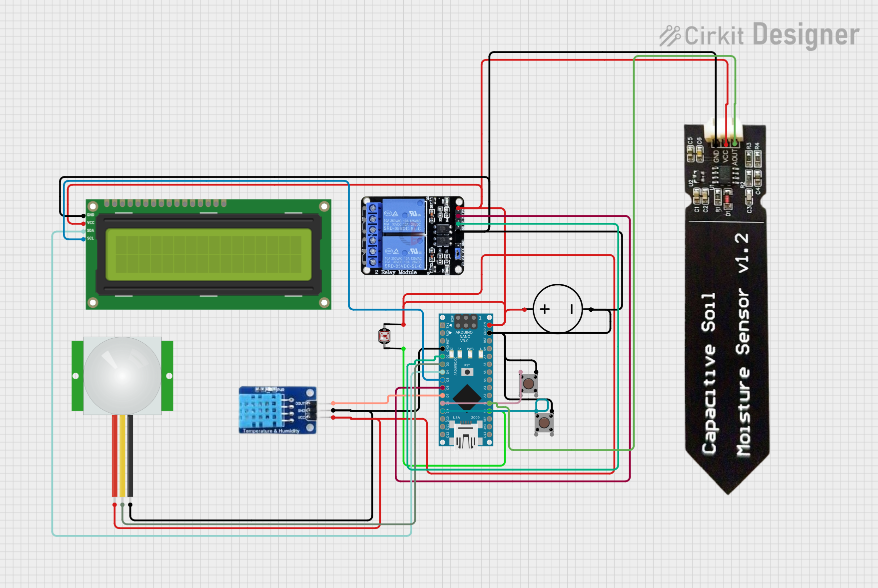
Greenhouse Automation System Circuit Documentation
Summary
The Greenhouse Automation System is designed to automate the environmental control of a greenhouse. It features an Arduino Nano microcontroller that interfaces with various sensors and actuators to monitor and adjust conditions such as temperature, humidity, soil moisture, and light. The system allows for manual overrides for watering and lighting through push buttons and includes an LCD for real-time status display. The circuit is powered by a DC power source and includes a PIR sensor for motion detection, a DHT11 sensor for temperature and humidity readings, a capacitive soil moisture sensor, an LDR for light level detection, and a two-channel relay module for controlling power to external devices such as a water pump and lights.
Component List
Arduino Nano
A compact microcontroller board based on the ATmega328P, featuring digital and analog I/O pins.
DHT11
A basic, ultra-low-cost digital temperature and humidity sensor.
Capacitive Soil Moisture Sensor V1.2
A sensor for measuring the moisture content in soil.
I2C LCD 16x2 Screen
A 16x2 character LCD display that uses the I2C communication protocol.
Two Channel Relay 5V
A module with two independent 5V relays that can control high power devices.
DC Power Source
A power supply unit that provides a DC voltage to power the circuit.
Photocell (LDR)
A light-dependent resistor whose resistance changes with light intensity.
Pushbutton
A simple switch mechanism for controlling some aspect of a machine or a process.
PIR Sensor
A passive infrared sensor that detects motion by measuring changes in the infrared levels emitted by surrounding objects.
Wiring Details
Arduino Nano
GNDconnected to the common ground net.D2connected to Relay IN1 (Water Pump).D3connected to PIR Sensor SIG.D4connected to LCD SDA.D5connected to LCD SCL.D6connected to Relay IN2 (Lights).D7connected to DHT11 DATA.D8connected to Water Pushbutton Pin 1 (in).D9connected to Light Pushbutton Pin 1 (in).VINconnected to the positive voltage net.A1connected to Soil Moisture Sensor AOUT.A0connected to LDR pin 0.
DHT11
DATAconnected to Arduino Nano D7.GNDconnected to the common ground net.VCCconnected to the positive voltage net.
Capacitive Soil Moisture Sensor V1.2
GNDconnected to the common ground net.VCCconnected to the positive voltage net.AOUTconnected to Arduino Nano A1.
I2C LCD 16x2 Screen
SCLconnected to Arduino Nano D5.SDAconnected to Arduino Nano D4.VCC (5V)connected to the positive voltage net.GNDconnected to the common ground net.
Two Channel Relay 5V
VCCconnected to the positive voltage net.IN2connected to Arduino Nano D6.IN1connected to Arduino Nano D2.GNDconnected to the common ground net.
DC Power Source
Groundconnected to the common ground net.Positiveconnected to the positive voltage net.
Photocell (LDR)
pin 0connected to Arduino Nano A0.pin 1connected to the positive voltage net.
Pushbutton (Water)
Pin 1 (in)connected to Arduino Nano D8.Pin 3 (out)connected to the common ground net.
Pushbutton (Light)
Pin 1 (in)connected to Arduino Nano D9.Pin 3 (out)connected to the common ground net.
PIR Sensor
SIGconnected to Arduino Nano D3.GNDconnected to the common ground net.VDDconnected to the positive voltage net.
Documented Code
/*
 * Greenhouse Automation System
 * This Arduino sketch controls a greenhouse system with automated watering,
 * light control, and displays soil/air humidity and temperature on an LCD.
 * The system includes manual overrides for light and watering with push
 * buttons, and automatic shutoff after a delay or when desired humidity is
 * reached. The LCD backlight is only on during the night.
 */

#include <Wire.h>
#include <LiquidCrystal_I2C.h>
#include <DHT.h>

// Pin definitions
#define DHTPIN 7
#define DHTTYPE DHT11
#define SOIL_MOISTURE_PIN A1
#define LDR_PIN A0
#define RELAY_WATER_PIN 2
#define RELAY_LIGHT_PIN 6
#define PIR_PIN 3
#define BUTTON_WATER_PIN 8
#define BUTTON_LIGHT_PIN 9
#define LCD_BACKLIGHT_PIN 10

// Timing constants
#define WATERING_TIMEOUT 1800000 // 30 minutes
#define LIGHT_TIMEOUT 300000 // 5 minutes

// Global variables
DHT dht(DHTPIN, DHTTYPE);
LiquidCrystal_I2C lcd(0x27, 16, 2);
unsigned long lastWateringTime = 0;
unsigned long lastLightTime = 0;
bool isWatering = false;
bool isLightOn = false;

void setup() {
  pinMode(RELAY_WATER_PIN, OUTPUT);
  pinMode(RELAY_LIGHT_PIN, OUTPUT);
  pinMode(BUTTON_WATER_PIN, INPUT_PULLUP);
  pinMode(BUTTON_LIGHT_PIN, INPUT_PULLUP);
  pinMode(PIR_PIN, INPUT);
  pinMode(LCD_BACKLIGHT_PIN, OUTPUT);
  digitalWrite(RELAY_WATER_PIN, HIGH); // Relay off
  digitalWrite(RELAY_LIGHT_PIN, HIGH); // Relay off
  dht.begin();
  lcd.init();
  lcd.backlight();
  lcd.setCursor(0, 0);
  lcd.print("Greenhouse System");
  delay(2000);
  lcd.clear();
}

void loop() {
  unsigned long currentTime = millis();
  float soilMoisture = analogRead(SOIL_MOISTURE_PIN);
  float ldrValue = analogRead(LDR_PIN);
  float humidity = dht.readHumidity();
  float temperature = dht.readTemperature();
  bool pirState = digitalRead(PIR_PIN);
  bool buttonWaterState = digitalRead(BUTTON_WATER_PIN) == LOW;
  bool buttonLightState = digitalRead(BUTTON_LIGHT_PIN) == LOW;

  // Update LCD
  lcd.setCursor(0, 0);
  lcd.print("Temp: ");
  lcd.print(temperature);
  lcd.print("C");
  lcd.setCursor(0, 1);
  lcd.print("Humidity: ");
  lcd.print(humidity);
  lcd.print("%");

  // Control LCD backlight
  if (ldrValue < 500) {
    digitalWrite(LCD_BACKLIGHT_PIN, HIGH);
  } else {
    digitalWrite(LCD_BACKLIGHT_PIN, LOW);
  }

  // Watering control
  if (buttonWaterState || (soilMoisture < 300 && !isWatering)) {
    digitalWrite(RELAY_WATER_PIN, LOW); // Relay on
    isWatering = true;
    lastWateringTime = currentTime;
  }
  if (isWatering && (currentTime - lastWateringTime > WATERING_TIMEOUT || soilMoisture > 700)) {
    digitalWrite(RELAY_WATER_PIN, HIGH); // Relay off
    isWatering = false;
  }

  // Light control
  if (buttonLightState || (pirState && ldrValue < 500 && !isLightOn)) {
    digitalWrite(RELAY_LIGHT_PIN, LOW); // Relay on
    isLightOn = true;
    lastLightTime = currentTime;
  }
  if (isLightOn && (currentTime - lastLightTime > LIGHT_TIMEOUT)) {
    digitalWrite(RELAY_LIGHT_PIN, HIGH); // Relay off
    isLightOn = false;
  }

  delay(1000); // Update every second
}
This code is responsible for reading sensor data, controlling the relays based on sensor inputs and manual button presses, and updating the LCD display with the current temperature and humidity. It also includes logic for turning the LCD backlight on during low light conditions and managing the timing for watering and lighting control.