
Arduino-Based Smart Weather Station with LCD Display and Solar Power
View and Edit Project In Cirkit Designer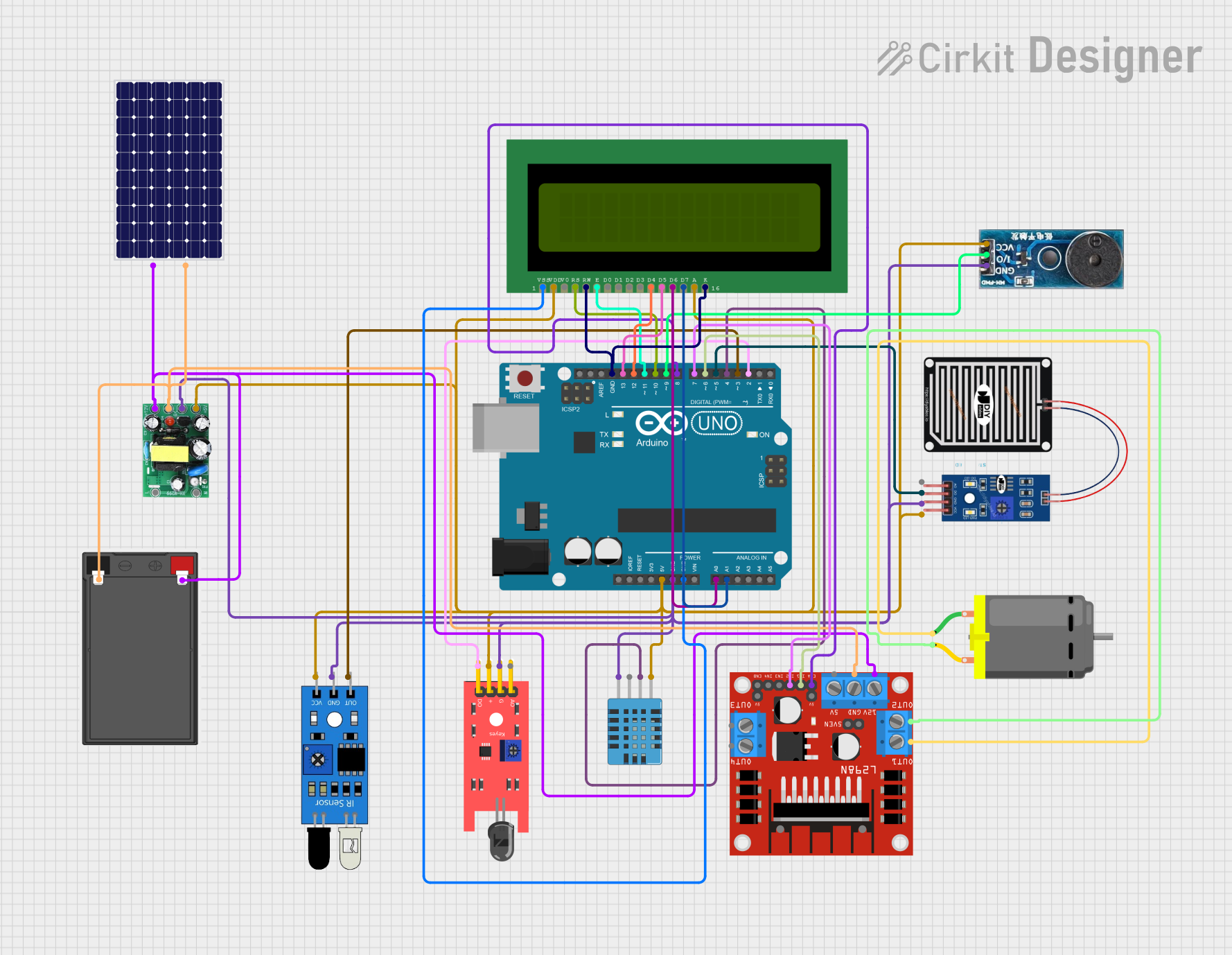
Circuit Documentation
Summary
This document provides a detailed overview of a circuit that integrates various sensors, an LCD display, a motor driver, and a microcontroller (Arduino UNO). The circuit is designed to monitor environmental conditions using sensors, display information on an LCD, and control a DC motor. Power is supplied through a combination of a solar panel, battery, and an AC-DC PSU board.
Component List
LCD 16x2 (Wokwi Compatible)
- Pins: VSS, VDD, V0, RS, RW, E, D0, D1, D2, D3, D4, D5, D6, D7, A, K
- Description: 16x2 character LCD display
- Purpose: Display information
Solar Panel
- Pins: +, -
- Description: Solar panel for power generation
- Purpose: Power supply
AC-DC PSU Board 220V-5V&12V
- Pins: AC-N, AC-L, +5V, GND, +12V
- Description: Power supply unit converting AC to 5V and 12V DC
- Purpose: Power supply
KY-026 Flame Sensor
- Pins: A0, GND, VCC, D0
- Description: Flame detection sensor
- Purpose: Detect flame presence
Arduino UNO
- Pins: UNUSED, IOREF, Reset, 3.3V, 5V, GND, Vin, A0, A1, A2, A3, A4, A5, SCL, SDA, AREF, D13, D12, D11, D10, D9, D8, D7, D6, D5, D4, D3, D2, D1, D0
- Description: Microcontroller board
- Purpose: Control and processing unit
IR Sensor
- Pins: out, gnd, vcc
- Description: Infrared sensor
- Purpose: Detect obstacles
DHT11 Humidity and Temperature Sensor
- Pins: VDD, DATA, NULL, GND
- Description: Humidity and temperature sensor
- Purpose: Measure environmental humidity and temperature
L298N DC Motor Driver
- Pins: OUT1, OUT2, 12V, GND, 5V, OUT3, OUT4, 5V-ENA-JMP-I, 5V-ENA-JMP-O, +5V-J1, +5V-J2, ENA, IN1, IN2, IN3, IN4, ENB
- Description: Dual H-Bridge motor driver
- Purpose: Control DC motors
DC Motor
- Pins: pin 1, pin 2
- Description: DC motor
- Purpose: Actuation
Rain Sensor
- Pins: AO, DO, GRD, VCC
- Description: Rain detection sensor
- Purpose: Detect rain
Buzzer Module
- Pins: GND, Vcc, I/O
- Description: Buzzer for sound alerts
- Purpose: Sound alerts
Battery
- Pins: -, +
- Description: Battery for power storage
- Purpose: Power supply
Wiring Details
LCD 16x2 (Wokwi Compatible)
- VSS: Connected to Arduino UNO GND
- VDD: Connected to Arduino UNO 5V
- V0: Not connected
- RS: Connected to Arduino UNO D10
- RW: Connected to Arduino UNO GND
- E: Connected to Arduino UNO D11
- D0: Not connected
- D1: Not connected
- D2: Not connected
- D3: Not connected
- D4: Connected to Arduino UNO D12
- D5: Connected to Arduino UNO D13
- D6: Connected to Arduino UNO A0
- D7: Connected to Arduino UNO A1
- A: Connected to Arduino UNO 5V
- K: Connected to Arduino UNO GND
Solar Panel
- +: Connected to Battery +
- -: Connected to Battery -
AC-DC PSU Board 220V-5V&12V
- AC-N: Not connected
- AC-L: Not connected
- +5V: Connected to Arduino UNO 5V
- GND: Connected to Arduino UNO GND
- +12V: Connected to L298N DC Motor Driver 12V
KY-026 Flame Sensor
- A0: Not connected
- GND: Connected to Arduino UNO GND
- VCC: Connected to Arduino UNO 5V
- D0: Connected to Arduino UNO D2
Arduino UNO
- GND: Connected to LCD 16x2 VSS, LCD 16x2 RW, LCD 16x2 K, KY-026 Flame Sensor GND, IR Sensor gnd, DHT11 Humidity and Temperature Sensor GND, Rain Sensor GRD, Buzzer Module GND, AC-DC PSU Board GND
- 5V: Connected to LCD 16x2 VDD, LCD 16x2 A, KY-026 Flame Sensor VCC, IR Sensor vcc, DHT11 Humidity and Temperature Sensor VDD, Rain Sensor VCC, Buzzer Module Vcc, AC-DC PSU Board +5V
- D10: Connected to LCD 16x2 RS
- D11: Connected to LCD 16x2 E
- D12: Connected to LCD 16x2 D4
- D13: Connected to LCD 16x2 D5
- A0: Connected to LCD 16x2 D6
- A1: Connected to LCD 16x2 D7
- D2: Connected to KY-026 Flame Sensor D0
- D9: Connected to Buzzer Module I/O
- D8: Connected to L298N DC Motor Driver ENA
- D7: Connected to L298N DC Motor Driver IN2
- D6: Connected to L298N DC Motor Driver IN1
- D5: Connected to Rain Sensor DO
- D4: Connected to DHT11 Humidity and Temperature Sensor DATA
- D3: Connected to IR Sensor out
IR Sensor
- out: Connected to Arduino UNO D3
- gnd: Connected to Arduino UNO GND
- vcc: Connected to Arduino UNO 5V
DHT11 Humidity and Temperature Sensor
- VDD: Connected to Arduino UNO 5V
- DATA: Connected to Arduino UNO D4
- NULL: Not connected
- GND: Connected to Arduino UNO GND
L298N DC Motor Driver
- OUT1: Connected to DC Motor pin 1
- OUT2: Connected to DC Motor pin 2
- 12V: Connected to AC-DC PSU Board +12V
- GND: Connected to AC-DC PSU Board GND
- 5V: Not connected
- OUT3: Not connected
- OUT4: Not connected
- 5V-ENA-JMP-I: Not connected
- 5V-ENA-JMP-O: Not connected
- +5V-J1: Not connected
- +5V-J2: Not connected
- ENA: Connected to Arduino UNO D8
- IN1: Connected to Arduino UNO D6
- IN2: Connected to Arduino UNO D7
- IN3: Not connected
- IN4: Not connected
- ENB: Not connected
DC Motor
- pin 1: Connected to L298N DC Motor Driver OUT1
- pin 2: Connected to L298N DC Motor Driver OUT2
Rain Sensor
- AO: Not connected
- DO: Connected to Arduino UNO D5
- GRD: Connected to Arduino UNO GND
- VCC: Connected to Arduino UNO 5V
Buzzer Module
- GND: Connected to Arduino UNO GND
- Vcc: Connected to Arduino UNO 5V
- I/O: Connected to Arduino UNO D9
Battery
- -: Connected to Solar Panel -
- +: Connected to Solar Panel +
Code Documentation
Arduino UNO Code
void setup() {
  // put your setup code here, to run once:

}

void loop() {
  // put your main code here, to run repeatedly:

}
This code is a basic template for the Arduino UNO. The setup() function is where you initialize your components and settings, and