
Arduino-Controlled Line Following Robot with Dual DC Motors and IR Array
View and Edit Project In Cirkit Designer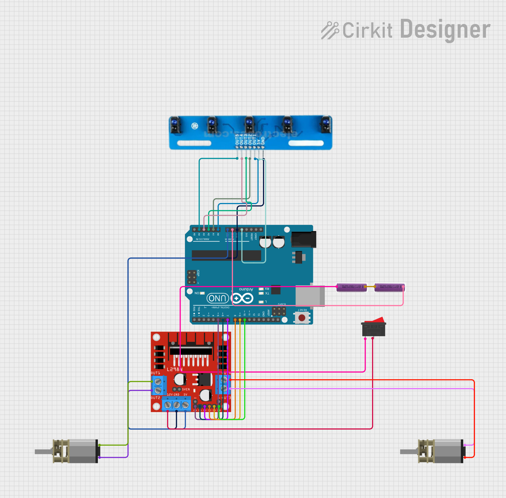
Circuit Documentation
Summary
This circuit is designed to interface an Arduino UNO with a 5 channel IR array, two DC Mini Metal Gear Motors through an L298N DC motor driver, and is powered by two 3.7V batteries connected in series with a rocker switch for power control. The Arduino UNO reads sensor data from the IR array and controls the motor driver, which in turn drives the motors.
Component List
5 Channel IR Array
- Pins: A5, A4, A3, A2, A1, VCC, GND
- Description: An array of 5 infrared sensors used for line tracking or obstacle detection.
Arduino UNO
- Pins: UNUSED, IOREF, Reset, 3.3V, 5V, GND, Vin, A0-A5, SCL, SDA, AREF, D0-D13
- Description: A microcontroller board based on the ATmega328P, widely used for prototyping and educational purposes.
3.7V Battery
- Pins: +, -
- Description: A single-cell lithium-polymer (LiPo) battery providing a nominal voltage of 3.7V.
Rocker Switch
- Pins: 1, 2
- Description: A simple on-off switch to control the power flow in the circuit.
L298N DC Motor Driver
- Pins: OUT1, OUT2, 12V, GND, 5V, OUT3, OUT4, 5V-ENA-JMP-I, 5V-ENA-JMP-O, +5V-J1, +5V-J2, ENA, IN1, IN2, IN3, IN4, ENB
- Description: A dual H-bridge motor driver capable of driving two DC motors or one stepper motor.
DC Mini Metal Gear Motor
- Pins: IN1, IN2
- Description: A compact geared DC motor suitable for a wide range of applications.
Wiring Details
5 Channel IR Array
- VCC: Connected to Arduino UNO 5V
- GND: Connected to Arduino UNO GND
- A1-A5: Connected to Arduino UNO A0-A4 respectively
Arduino UNO
- 5V: Provides power to the 5 channel IR array
- GND: Common ground for the circuit
- Vin: Receives power from the L298N DC motor driver 5V output
- A0-A4: Receives sensor data from the 5 channel IR array A1-A5
- D5-D10: Control signals for the L298N DC motor driver
3.7V Batteries
- Series Connection: The positive terminal of one battery is connected to the negative terminal of the other battery.
- Rocker Switch: Connected in series with the batteries to control power to the L298N DC motor driver.
Rocker Switch
- Pin 1: Connected to the positive terminal of one 3.7V battery
- Pin 2: Connected to the 12V input of the L298N DC motor driver
L298N DC Motor Driver
- 12V: Receives power from the rocker switch
- GND: Connected to Arduino UNO GND
- 5V: Provides power to Arduino UNO Vin
- ENA, ENB: Enable signals for the motor driver channels, connected to Arduino UNO D5 and D10
- IN1-IN4: Control signals for the motors, connected to Arduino UNO D6-D9
- OUT1-OUT4: Connected to the DC Mini Metal Gear Motors
DC Mini Metal Gear Motors
- IN1, IN2: Each motor has two input pins connected to the corresponding OUT1-OUT4 pins on the L298N DC motor driver.
Documented Code
Arduino UNO Code (sketch.ino)
void setup() {
  // put your setup code here, to run once:

}

void loop() {
  // put your main code here, to run repeatedly:

}
This code is a template and does not contain any functional code. It needs to be populated with the setup and loop functions to initialize the pins and implement the control logic for reading the IR array and controlling the motors through the L298N driver.