
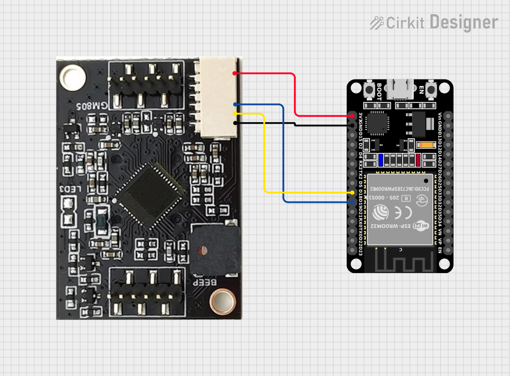
Circuit Documentation
Summary of the Circuit
The circuit in question consists of two main components: an ESP32 microcontroller with a 30-pin layout and a GM805 module. The ESP32 is a versatile and powerful microcontroller with Wi-Fi and Bluetooth capabilities, suitable for a wide range of applications from simple to complex IoT devices. The GM805 module is typically used for GPS tracking and navigation purposes, providing location data to the connected microcontroller.
The ESP32 microcontroller is responsible for processing data and controlling the operation of the circuit. It communicates with the GM805 module via serial communication, receiving GPS data that can be used for location-based services.
Component List
ESP32 (30 pin)
- Description: A 30-pin microcontroller with Wi-Fi and Bluetooth capabilities.
- Pins: EN, VP, VN, D34, D35, D32, D33, D25, D26, D27, D14, D12, D13, GND, Vin, D23, D22, TX0, RX0, D21, D19, D18, D5, TX2, RX2, D4, D2, D15, 3V3
GM805
- Description: A GPS module used for tracking and navigation.
- Pins: 3.3v, GND, TXD, RXD
Wiring Details
ESP32 (30 pin)
- 3V3: Connected to the 3.3v pin of the GM805 module to provide power.
- GND: Connected to the GND pin of the GM805 module to establish a common ground.
- D18 (TX0): Connected to the TXD pin of the GM805 module for transmitting data to the GPS module.
- D19 (RX0): Connected to the RXD pin of the GM805 module for receiving data from the GPS module.
GM805
- 3.3v: Receives power from the 3V3 pin of the ESP32 microcontroller.
- GND: Connected to the GND pin of the ESP32 microcontroller to establish a common ground.
- TXD: Transmits data to the D18 (TX0) pin of the ESP32 microcontroller.
- RXD: Receives data from the D19 (RX0) pin of the ESP32 microcontroller.
Documented Code
No code has been provided for the microcontroller. For the circuit to function, embedded code needs to be written and uploaded to the ESP32 microcontroller to handle initialization, configuration of the serial communication with the GM805 module, and processing of the GPS data received.
Typically, the code would initialize the serial communication at the appropriate baud rate, set up the necessary GPIO pins, and include a main loop to handle the reading of data from the GM805 module and any other logic required for the application.
Since no code is available, it is recommended to develop the firmware considering the following aspects:
- Initialization of the ESP32 peripherals.
- Configuration of the UART interface for communication with the GM805 module.
- Parsing of the GPS data received from the GM805 module.
- Implementation of error handling and data validation.
- Power management for energy-efficient operation if required.
The code should be thoroughly tested to ensure reliable operation of the circuit.