
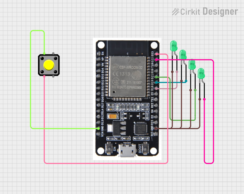
Circuit Documentation
Summary
This circuit consists of an ESP32 microcontroller, a pushbutton, and four green LEDs. The pushbutton is used to trigger a random lighting sequence of the LEDs. When the button is pressed, a random number between 1 and 4 is generated, and the corresponding number of LEDs light up.
Component List
Pushbutton
- Description: A simple pushbutton switch.
- Pins: Pin 1, Pin 2, Pin 3, Pin 4
ESP32
- Description: A powerful microcontroller with Wi-Fi and Bluetooth capabilities.
- Pins: EN, VP, VN, D34, D35, D32, D33, D25, D26, D27, D14, D12, D13, GND, VIN, 3V3, D15, D2, D4, RX2, TX2, D5, D18, D19, D21, RX0, TX0, D22, D23, BOOT
LED: Two Pin (green)
- Description: A green LED with two pins.
- Pins: Cathode, Anode
LED: Two Pin (green)
- Description: A green LED with two pins.
- Pins: Cathode, Anode
LED: Two Pin (green)
- Description: A green LED with two pins.
- Pins: Cathode, Anode
LED: Two Pin (green)
- Description: A green LED with two pins.
- Pins: Cathode, Anode
Wiring Details
Pushbutton
- Pin 1: Connected to GND of ESP32
- Pin 2: Connected to D23 of ESP32
- Pin 3: Not connected
- Pin 4: Not connected
ESP32
- D23: Connected to Pin 2 of Pushbutton
- GND: Connected to Pin 1 of Pushbutton and Cathodes of all LEDs
- D18: Connected to Anode of LED 1
- D19: Connected to Anode of LED 2
- D21: Connected to Anode of LED 3
- D22: Connected to Anode of LED 4
LED 1
- Cathode: Connected to GND of ESP32
- Anode: Connected to D18 of ESP32
LED 2
- Cathode: Connected to GND of ESP32
- Anode: Connected to D19 of ESP32
LED 3
- Cathode: Connected to GND of ESP32
- Anode: Connected to D21 of ESP32
LED 4
- Cathode: Connected to GND of ESP32
- Anode: Connected to D22 of ESP32
Code Documentation
#define BUTTON_PIN 23
#define LED1_PIN 18
#define LED2_PIN 19
#define LED3_PIN 21
#define LED4_PIN 22

void setup() {
  pinMode(BUTTON_PIN, INPUT_PULLUP);
  pinMode(LED1_PIN, OUTPUT);
  pinMode(LED2_PIN, OUTPUT);
  pinMode(LED3_PIN, OUTPUT);
  pinMode(LED4_PIN, OUTPUT);

  randomSeed(analogRead(0)); // Seed the random number generator
}

void loop() {
  static bool buttonPressed = false;
  int buttonState = digitalRead(BUTTON_PIN);

  if (buttonState == LOW && !buttonPressed) {
    buttonPressed = true;
    int roll = random(1, 5); // Generate a random number between 1 and 4

    // Turn off all LEDs
    digitalWrite(LED1_PIN, LOW);
    digitalWrite(LED2_PIN, LOW);
    digitalWrite(LED3_PIN, LOW);
    digitalWrite(LED4_PIN, LOW);

    // Light up LEDs based on the roll
    if (roll >= 1) digitalWrite(LED1_PIN, HIGH);
    if (roll >= 2) digitalWrite(LED2_PIN, HIGH);
    if (roll >= 3) digitalWrite(LED3_PIN, HIGH);
    if (roll >= 4) digitalWrite(LED4_PIN, HIGH);
  } else if (buttonState == HIGH) {
    buttonPressed = false;
  }

  delay(100);
}
This code initializes the pushbutton and LEDs, and in the main loop, it checks if the button is pressed. If pressed, it generates a random number between 1 and 4 and lights up the corresponding number of LEDs. The LEDs are turned off before lighting up the new sequence.