Arduino UNO Based Calculator with LCD Display and Membrane Keypad
Circuit Documentation
Summary
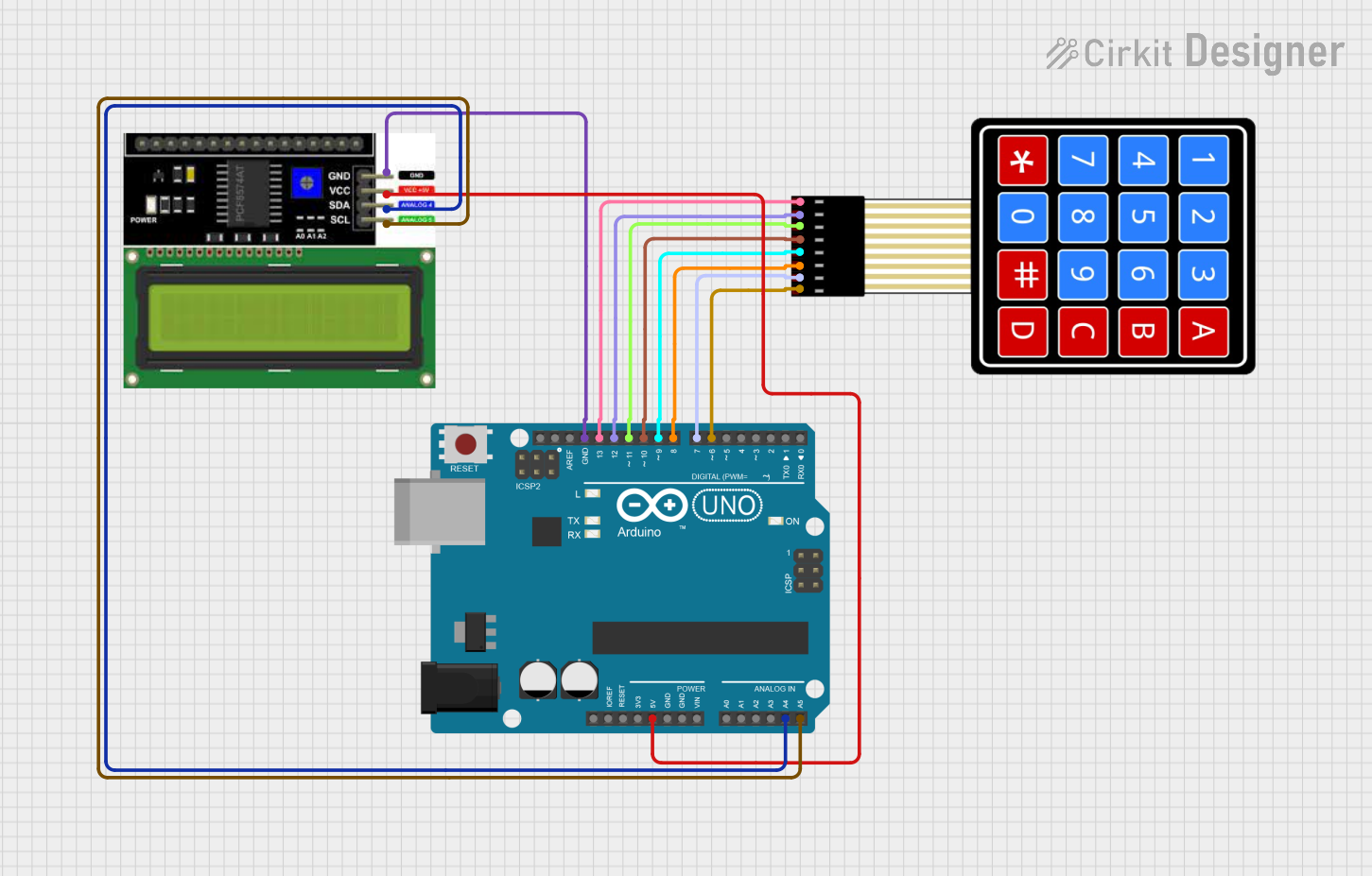
This circuit is designed to function as an Arduino-based calculator with an LCD display and a 4x4 membrane matrix keypad. The Arduino UNO serves as the central processing unit, interfacing with the keypad for user input and the LCD display for output. The keypad allows users to input numbers and arithmetic operations, while the LCD displays the input and the calculated results.
Component List
Arduino UNO
- Description: A microcontroller board based on the ATmega328P.
- Pins: UNUSED, IOREF, Reset, 3.3V, 5V, GND, Vin, A0-A5, SCL, SDA, AREF, D0-D13
- Purpose: Acts as the main controller for the calculator, processing keypad inputs and driving the LCD display.
LCD I2C Display
- Description: An alphanumeric liquid crystal display with an I2C interface.
- Pins: GND, VCC, SDA, SCL
- Purpose: Displays the numbers inputted by the user as well as the calculation results.
4X4 Membrane Matrix Keypad
- Description: A simple interface for user input, featuring 16 buttons arranged in a 4x4 grid.
- Pins: R1, R2, R3, R4, C1, C2, C3, C4
- Purpose: Allows the user to input numbers and arithmetic operations into the calculator.
Wiring Details
Arduino UNO
- 5V to LCD I2C Display VCC
- GND to LCD I2C Display GND
- A4 (SDA) to LCD I2C Display SDA
- A5 (SCL) to LCD I2C Display SCL
- D13 to Keypad R1
- D12 to Keypad R2
- D11 to Keypad R3
- D10 to Keypad R4
- D9 to Keypad C1
- D8 to Keypad C2
- D7 to Keypad C3
- D6 to Keypad C4
LCD I2C Display
- VCC connected to Arduino UNO 5V
- GND connected to Arduino UNO GND
- SDA connected to Arduino UNO A4 (SDA)
- SCL connected to Arduino UNO A5 (SCL)
4X4 Membrane Matrix Keypad
- R1 connected to Arduino UNO D13
- R2 connected to Arduino UNO D12
- R3 connected to Arduino UNO D11
- R4 connected to Arduino UNO D10
- C1 connected to Arduino UNO D9
- C2 connected to Arduino UNO D8
- C3 connected to Arduino UNO D7
- C4 connected to Arduino UNO D6
Documented Code
/**
   Arduino Calculator

   Copyright (C) 2020, Uri Shaked.
   Released under the MIT License.
*/

#include <LiquidCrystal.h>
#include <Keypad.h>

/* Display */
LiquidCrystal lcd(12, 11, 10, 9, 8, 7);

/* Keypad setup */
const byte KEYPAD_ROWS = 4;
const byte KEYPAD_COLS = 4;
byte rowPins[KEYPAD_ROWS] = {5, 4, 3, 2}; // Incorrect pin mapping, should be D13, D12, D11, D10
byte colPins[KEYPAD_COLS] = {A3, A2, A1, A0}; // Incorrect pin mapping, should be D9, D8, D7, D6
char keys[KEYPAD_ROWS][KEYPAD_COLS] = {
  {'1', '2', '3', '+'},
  {'4', '5', '6', '-'},
  {'7', '8', '9', '*'},
  {'.', '0', '=', '/'}
};

Keypad keypad = Keypad(makeKeymap(keys), rowPins, colPins, KEYPAD_ROWS, KEYPAD_COLS);

uint64_t value = 0;

void showSpalshScreen() {
  lcd.print("GoodArduinoCode");
  lcd.setCursor(3, 1);
  String message = "Calculator";
  for (byte i = 0; i < message.length(); i++) {
    lcd.print(message[i]);
    delay(50);
  }
  delay(500);
}

void updateCursor() {
  if (millis() / 250 % 2 == 0 ) {
    lcd.cursor();
  } else {
    lcd.noCursor();
  }
}

void setup() {
  Serial.begin(115200);
  lcd.begin(16, 2);

  showSpalshScreen();
  lcd.clear();
  lcd.cursor();

  lcd.setCursor(1, 0);
}

char operation = 0;
String memory = "";
String current = "";
uint64_t currentDecimal;
bool decimalPoint = false;

double calculate(char operation, double left, double right) {
  switch (operation) {
    case '+': return left + right;
    case '-': return left - right;
    case '*': return left * right;
    case '/': return left / right;
  }
}

void processInput(char key) {
  if ('-' == key && current == "") {
    current = "-";
    lcd.print("-");
    return;
  }

  switch (key) {
    case '+':
    case '-':
    case '*':
    case '/':
      if (!operation) {
        memory = current;
        current = "";
      }
      operation = key;
      lcd.setCursor(0, 1);
      lcd.print(key);
      lcd.setCursor(current.length() + 1, 1);
      return;

    case '=':
      float leftNum = memory.toDouble();
      float rightNum = current.toDouble();
      memory = String(calculate(operation, leftNum, rightNum));
      current = "";
      lcd.clear();
      lcd.setCursor(1, 0);
      lcd.print(memory);
      lcd.setCursor(0, 1);
      lcd.print(operation);
      return;

  }

  if ('.' == key && current.indexOf('.') >= 0) {
    return;
  }

  if ('.' != key && current == "0") {
    current = String(key);
  } else if (key) {
    current += String(key);
  }

  lcd.print(key);
}

void loop() {
  updateCursor();

  char key = keypad.getKey();
  if (key) {
    processInput(key);
  }
}
Note: The code provided has incorrect pin mappings for the keypad. The rowPins and colPins arrays should be updated to match the actual wiring as specified in the wiring details section. The corrected pin mappings should be:
byte rowPins[KEYPAD_ROWS] = {13, 12, 11, 10}; // Corrected pin mapping for rows
byte colPins[KEYPAD_COLS] = {9, 8, 7, 6}; // Corrected pin mapping for columns
The rest of the code handles the initialization of the LCD and keypad, the splash screen display, cursor blinking, input processing, and calculation logic. The loop() function continuously checks for key presses and processes them accordingly.