Arduino UNO Controlled Light-Responsive LED Array
Circuit Documentation
Summary
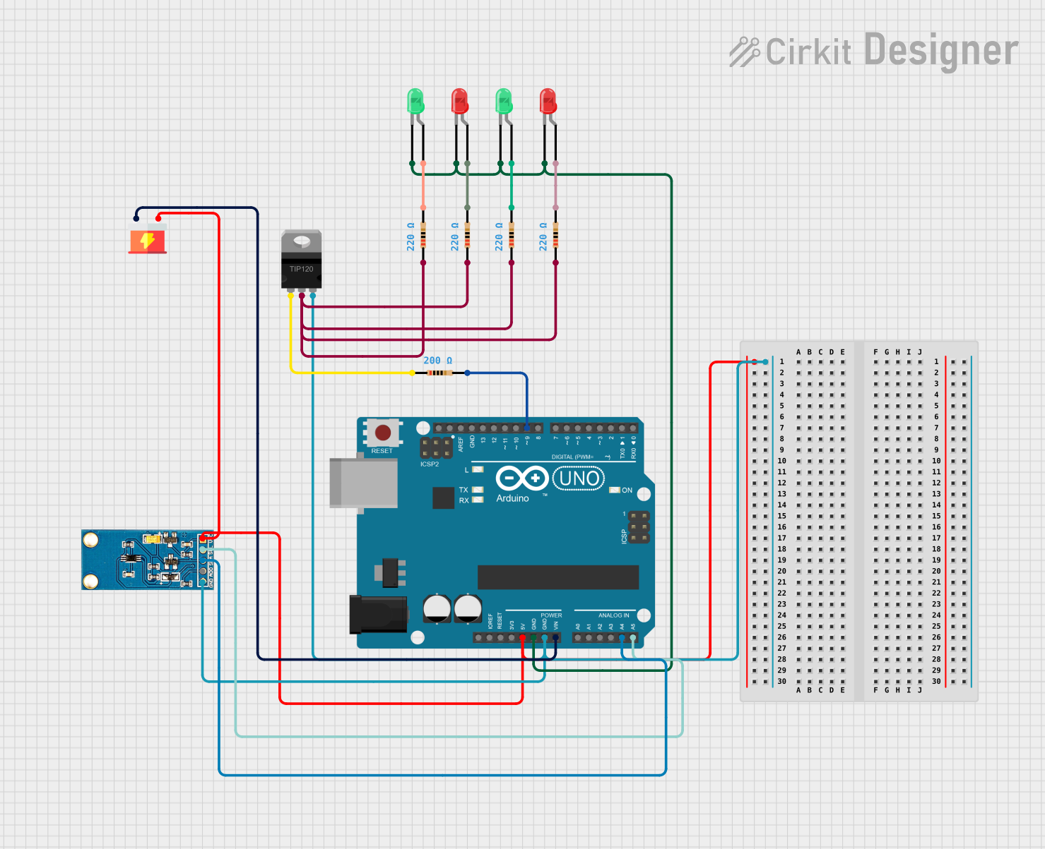
This circuit is designed to control the brightness of a set of LEDs based on the ambient light level detected by a light sensor. The core of the circuit is an Arduino UNO microcontroller, which reads the light sensor data and adjusts the LED brightness accordingly through a TIP120 Darlington Transistor. The LEDs are connected with resistors to limit the current, and the entire circuit is powered by a supply unit.
Component List
Arduino UNO
- Description: A microcontroller board based on the ATmega328P.
- Pins: UNUSED, IOREF, Reset, 3.3V, 5V, GND, Vin, A0-A5, SCL, SDA, AREF, D0-D13.
LED: Two Pin (red)
- Description: A red light-emitting diode.
- Pins: cathode, anode.
LED: Two Pin (green)
- Description: A green light-emitting diode.
- Pins: cathode, anode.
Light Sensor
- Description: A sensor that detects the ambient light level.
- Pins: VCC, SCL, SDA, ADD, GND.
TIP120 Hi-Current Darlington Transistor
- Description: A transistor used for controlling high current loads.
- Pins: BASE, COLLECTOR, EMITTER.
Resistor (200 Ohms)
- Description: A resistor with a resistance of 200 Ohms.
Resistor (220 Ohms)
- Description: A resistor with a resistance of 220 Ohms.
Supply
- Description: A power supply unit.
- Pins: VCC, GND.
Wiring Details
Arduino UNO
- 5V connected to Light Sensor VCC and Supply VCC.
- GND connected to Light Sensor GND, LED cathodes, and TIP120 EMITTER.
- A4 (SDA) connected to Light Sensor SDA.
- A5 (SCL) connected to Light Sensor SCL.
- D9 connected to Resistor (200 Ohms) pin2.
LED: Two Pin (red)
- Cathode connected to Arduino UNO GND.
- Anode connected to Resistor (220 Ohms) pin2.
LED: Two Pin (green)
- Cathode connected to Arduino UNO GND.
- Anode connected to Resistor (220 Ohms) pin2.
Light Sensor
- VCC connected to Arduino UNO 5V.
- SCL connected to Arduino UNO A5.
- SDA connected to Arduino UNO A4.
- GND connected to Arduino UNO GND.
TIP120 Hi-Current Darlington Transistor
- BASE connected to Resistor (200 Ohms) pin1.
- COLLECTOR connected to Resistor (220 Ohms) pin1.
- EMITTER connected to Arduino UNO GND.
Resistor (200 Ohms)
- Pin1 connected to TIP120 BASE.
- Pin2 connected to Arduino UNO D9.
Resistor (220 Ohms)
- Pin1 connected to TIP120 COLLECTOR.
- Pin2 connected to LED anode.
Supply
- VCC connected to Arduino UNO Vin.
- GND connected to Arduino UNO GND.
Documented Code
// Pin definitions
const int lightSensorPin = A4; // Analog pin for light sensor (SDA)
const int ledPin = 9;          // PWM pin for LED control (connected to TIP120 base)
int lightValue = 0;            // Variable to store light sensor value

void setup() {
  // Initialize serial communication for debugging
  Serial.begin(9600);

  // Set pin modes
  pinMode(lightSensorPin, INPUT);
  pinMode(ledPin, OUTPUT);
}

void loop() {
  // Read the light sensor value
  lightValue = analogRead(lightSensorPin);

  // Print the light sensor value to the Serial Monitor
  Serial.print("Light Sensor Value: ");
  Serial.println(lightValue);

  // Map the light sensor value to a PWM value (0-255)
  int pwmValue = map(lightValue, 0, 1023, 255, 0); // Invert to increase LED brightness in lower light

  // Set the LED brightness based on the light sensor value
  analogWrite(ledPin, pwmValue);

  // Delay before the next loop iteration
  delay(100);
}
This code is designed to run on the Arduino UNO microcontroller. It initializes the serial communication for debugging purposes, sets the pin modes for the light sensor and LED control, reads the light sensor value, maps it to a PWM value, and adjusts the LED brightness accordingly. The loop runs continuously with a delay of 100 milliseconds between iterations.