Cirkit Designer
Your all-in-one circuit design IDE
Home /
Project Documentation
Arduino UNO Based Motion-Activated LED System
Circuit Documentation
Summary of the Circuit
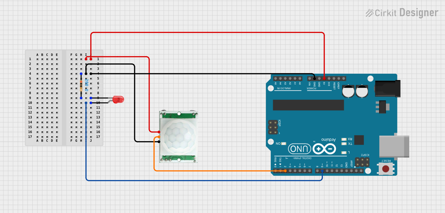
This circuit is designed to interface a PIR (Passive Infrared) motion sensor with an Arduino UNO microcontroller to detect motion and signal the presence of motion through a red LED. The PIR sensor is powered by the Arduino's 5V output and its ground is connected to the Arduino's ground. The sensor's output is connected to one of the Arduino's digital input pins. The LED is connected to another digital pin of the Arduino through a resistor to limit the current and protect the LED.
Component List
Arduino UNO
- Description: A microcontroller board based on the ATmega328P.
- Purpose: Acts as the central processing unit of the circuit, reading sensor data and controlling the LED.
- Pins Used: 5V, GND, D2, D9.
LED: Two Pin (red)
- Description: A basic red light-emitting diode.
- Purpose: Indicates the detection of motion when lit.
- Pins Used: Anode, Cathode.
PIR/Motion Sensor
- Description: A sensor that detects motion based on changes in infrared radiation.
- Purpose: Senses the presence of a moving object/person.
- Pins Used: VCC, GND, OUTPUT.
Resistor
- Description: A passive two-terminal electrical component that implements electrical resistance.
- Purpose: Limits the current flowing through the LED to prevent damage.
- Value: 200 Ohms.
Wiring Details
Arduino UNO
- 5V to PIR/Motion Sensor VCC
- GND to PIR/Motion Sensor GND and one end of the Resistor
- D2 to PIR/Motion Sensor OUTPUT
- D9 to LED Anode
LED: Two Pin (red)
- Anode to Arduino UNO D9
- Cathode to the other end of the Resistor
PIR/Motion Sensor
- VCC to Arduino UNO 5V
- GND to Arduino UNO GND
- OUTPUT to Arduino UNO D2
Resistor
- One end to Arduino UNO GND
- Other end to LED Cathode
Documented Code
Arduino UNO Code (sketch.ino)
void setup() {
  // put your setup code here, to run once:

}

void loop() {
  // put your main code here, to run repeatedly:

}
Note: The provided code is a template and does not contain any functional code to operate the circuit. The user is expected to write the necessary setup and loop functions to initialize the pins and handle the logic for the PIR sensor and LED.