
Circuit Documentation
Summary
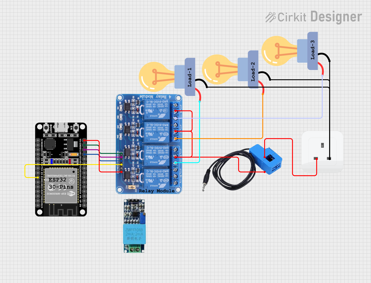
This circuit is designed to control multiple AC LED bulbs using an ESP32 microcontroller and a 4-channel 5V relay module. The ESP32 is responsible for triggering the relays, which in turn switch the LED bulbs on and off. A current sensor is included to monitor the current flow, and a voltage sensor could be added for voltage monitoring (though it is not wired in this design). The circuit is powered through a socket that provides the AC power to the bulbs and the current sensor.
Component List
ESP32 (30 pin)
- Description: A microcontroller with WiFi and Bluetooth capabilities.
- Purpose: Acts as the central control unit for the circuit, interfacing with the relay module to control the LED bulbs.
Relay 4 Channel 5v
- Description: A relay module with four channels that can be individually controlled.
- Purpose: Switches the LED bulbs on and off based on signals from the ESP32.
LED bulb AC / Bombillo AC
- Description: Standard AC-powered LED bulbs.
- Purpose: Provide lighting when powered.
Current Sensor
- Description: A sensor that measures the flow of electric current.
- Purpose: Monitors the current consumed by the circuit.
Socket
- Description: An AC power socket.
- Purpose: Provides AC power to the circuit.
Comments
- Description: Text placeholders for additional information or notes.
- Purpose: Used to include comments or annotations within the circuit design.
Wiring Details
ESP32 (30 pin)
- GND connected to Relay 4 Channel 5v GND
- Vin connected to Relay 4 Channel 5v VCC
- D12 connected to Relay 4 Channel 5v IN2
- D13 connected to Relay 4 Channel 5v IN1
- D18 connected to Relay 4 Channel 5v IN3
Relay 4 Channel 5v
- GND connected to ESP32 GND
- VCC connected to ESP32 Vin
- IN1 connected to ESP32 D13
- IN2 connected to ESP32 D12
- IN3 connected to ESP32 D18
- COM1, COM2, COM3 connected to Current Sensor Out_current
- NO1 connected to LED bulb AC (+) [Instance 1]
- NO2 connected to LED bulb AC (+) [Instance 2]
- NO3 connected to LED bulb AC (+) [Instance 3]
LED bulb AC / Bombillo AC (Instance 1)
- + connected to Relay 4 Channel 5v NO1
- - connected to Socket neutral
LED bulb AC / Bombillo AC (Instance 2)
- + connected to Relay 4 Channel 5v NO2
- - connected to Socket neutral
LED bulb AC / Bombillo AC (Instance 3)
- + connected to Relay 4 Channel 5v NO3
- - connected to Socket neutral
Current Sensor
- Out_current connected to Relay 4 Channel 5v COM1, COM2, COM3
- In_current connected to Socket life
Socket
- life connected to Current Sensor In_current
- neutral connected to LED bulb AC (-) [All instances]
Documented Code
ESP32 (30 pin) - sketch.ino
void setup() {
  // put your setup code here, to run once:

}

void loop() {
  // put your main code here, to run repeatedly:

}
Note: The provided code is a template and does not include specific functionality. It should be expanded to initialize the GPIO pins connected to the relay module and to handle the control logic for turning the LED bulbs on and off based on some criteria (e.g., sensor input, time of day, external commands via WiFi, etc.).