
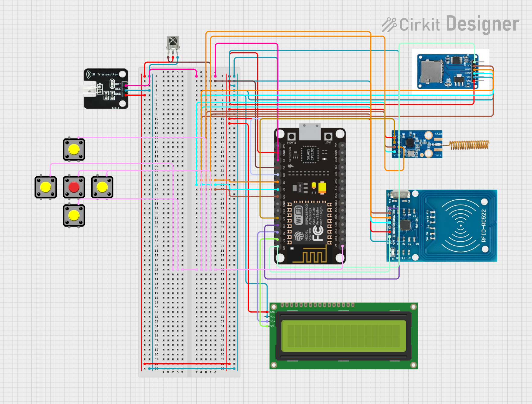
Circuit Documentation
Summary
This circuit is a multi-functional tool based on the ESP-8266 microcontroller. It integrates various modules including an RFID reader, an IR transmitter and receiver, an RF module, an SD card module, and an I2C LCD display. The circuit also includes multiple pushbuttons for user interaction. The ESP-8266 handles Wi-Fi connectivity and serves a web interface for controlling and monitoring the different modules.
Component List
ESP-8266 Controller
- Description: A Wi-Fi enabled microcontroller used to control the entire circuit.
- Pins: A0, RSV, SD3, SD5, SD1, CMD, D0, D1, D2, D3, D4, 3V3, GND, D5, D6, SD0, CLK, RST, EN, D7, D8, RX, TX, Vin, 5V
CC1101
- Description: An RF transceiver module used for wireless communication.
- Pins: VCC, GND, GDO0, SCLK, SO, GDO2, SI, CSN
RFID-RC522
- Description: An RFID reader module used for reading RFID tags.
- Pins: VCC (3.3V), RST, GND, IRQ, MISO, MOSI, SCK, SDA
SD Card Module
- Description: A module for interfacing with SD cards.
- Pins: CS, SCK, MOSI, MISO, VCC, GND
16x2 I2C LCD
- Description: An I2C-based LCD display for showing information.
- Pins: GND, VCC, SDA, SCL
Pushbutton
- Description: A simple pushbutton used for user input.
- Pins: Pin 2, Pin 1, Pin 3, Pin 4
VS1838B IR Receiver
- Description: An IR receiver module used for receiving IR signals.
- Pins: OUT, GND, VCC
IR Transmitter
- Description: An IR LED used for transmitting IR signals.
- Pins: DAT, VCC, GND
Wiring Details
ESP-8266 Controller
- A0: Connected to Pin 4 of all Pushbuttons
- D0: Connected to CS of SD Card Module and RST of RFID-RC522
- D1: Connected to SCL of 16x2 I2C LCD
- D2: Connected to SDA of 16x2 I2C LCD
- D3: Connected to SDA of RFID-RC522
- D4: Connected to GDO0 of CC1101
- D5: Connected to SCK of SD Card Module, SCLK of CC1101, and SCK of RFID-RC522
- D6: Connected to MISO of SD Card Module, SO of CC1101, and MISO of RFID-RC522
- D7: Connected to MOSI of SD Card Module, SI of CC1101, and MOSI of RFID-RC522
- D8: Connected to CSN of CC1101
- RX: Connected to OUT of VS1838B IR Receiver
- TX: Connected to DAT of IR Transmitter
- GND: Connected to GND of CC1101, RFID-RC522, SD Card Module, 16x2 I2C LCD, VS1838B IR Receiver, and IR Transmitter
- 3V3: Connected to VCC of CC1101, VCC (3.3V) of RFID-RC522, VCC of SD Card Module, VCC of 16x2 I2C LCD, VCC of VS1838B IR Receiver, and VCC of IR Transmitter
CC1101
- VCC: Connected to 3V3 of ESP-8266 Controller
- GND: Connected to GND of ESP-8266 Controller
- GDO0: Connected to D4 of ESP-8266 Controller
- SCLK: Connected to D5 of ESP-8266 Controller
- SO: Connected to D6 of ESP-8266 Controller
- SI: Connected to D7 of ESP-8266 Controller
- CSN: Connected to D8 of ESP-8266 Controller
RFID-RC522
- VCC (3.3V): Connected to 3V3 of ESP-8266 Controller
- RST: Connected to D0 of ESP-8266 Controller
- GND: Connected to GND of ESP-8266 Controller
- SCK: Connected to D5 of ESP-8266 Controller
- MISO: Connected to D6 of ESP-8266 Controller
- MOSI: Connected to D7 of ESP-8266 Controller
- SDA: Connected to D3 of ESP-8266 Controller
SD Card Module
- CS: Connected to D0 of ESP-8266 Controller
- SCK: Connected to D5 of ESP-8266 Controller
- MOSI: Connected to D7 of ESP-8266 Controller
- MISO: Connected to D6 of ESP-8266 Controller
- VCC: Connected to 3V3 of ESP-8266 Controller
- GND: Connected to GND of ESP-8266 Controller
16x2 I2C LCD
- GND: Connected to GND of ESP-8266 Controller
- VCC: Connected to 3V3 of ESP-8266 Controller
- SDA: Connected to D2 of ESP-8266 Controller
- SCL: Connected to D1 of ESP-8266 Controller
Pushbutton
- Pin 4: Connected to A0 of ESP-8266 Controller (for all pushbuttons)
VS1838B IR Receiver
- OUT: Connected to RX of ESP-8266 Controller
- GND: Connected to GND of ESP-8266 Controller
- VCC: Connected to 3V3 of ESP-8266 Controller
IR Transmitter
- DAT: Connected to TX of ESP-8266 Controller
- GND: Connected to GND of ESP-8266 Controller
- VCC: Connected to 3V3 of ESP-8266 Controller
Code Documentation
Main Code
#include <ESP8266WiFi.h>
#include <ESP8266WebServer.h>
#include <MFRC522.h>
#include <ELECHOUSE_CC1101.h>
#include <IRremoteESP8266.h>
#include <IRsend.h>
#include <IRrecv.h>
#include <IRutils.h>
#include <SD.h>
#include <Wire.h>
#include <LiquidCrystal_I2C.h>

// Wi-Fi credentials
const char* ssid = "Your_WiFi_SSID";
const char* password = "Your_WiFi_PASSWORD";

// Web server on port 80
ESP8266WebServer server(80);

// RFID Setup
#define RST_PIN D3
#define SDA_PIN D4
MFRC522 rfid(SDA_PIN, RST_PIN);

// CC1101 Setup
#define CC1101_CS_PIN D2

// IR Setup
#define IR_LED_PIN D1
IRsend irsend(IR_LED_PIN);
IRrecv irrecv(D5);
decode_results results;

// SD Card Setup
#define SD_CS_PIN D8

// LCD Setup
LiquidCrystal_I2C lcd(0x27, 16, 2);

// Button Setup
#define BTN_UP D6
#define BTN_DOWN D7
#define BTN_LEFT D9
#define BTN_RIGHT D10
#define BTN_SELECT D0

// Navigation variables
int currentMenu = 0;
const char* menus[] = {"RFID", "IR", "RF", "Wi-Fi Scan", "Files"};
const int numMenus = sizeof(menus) / sizeof(menus[0]);

// Function prototypes
void handleRoot();
void handleRFID();
void handleIR();
void handleRF();
void handleWiFiScan();
void handleFileList();
void updateLCD();
void handleButtonPress();

void setup() {
  Serial.begin(115200);

  // Wi-Fi Setup
  WiFi.begin(ssid, password);
  while (WiFi.status() != WL_CONNECTED) {
    delay(1000);
    Serial.println("Connecting to Wi-Fi...");
  }
  Serial.println("Wi-Fi connected. IP address: " + WiFi.localIP().toString());

  // Web Server Setup
  server.on("/", handleRoot);
  server.on("/rfid", handleRFID);
  server.on("/ir", handleIR);
  server.on("/rf", handleRF);
  server.on("/wifi_scan", handleWiFiScan);
  server.on("/files", handleFileList);
  server.begin();

  // RFID Setup
  SPI.begin();
  rfid.PCD_Init();

  // CC1101 Setup
  ELECHOUSE_cc1101.setCS(CC1101_CS_PIN);
  ELECHOUSE_cc1101.Init();

  // IR