Cirkit Designer
Your all-in-one circuit design IDE
Home /
Project Documentation
Arduino-Controlled Environment Monitoring System with Relay-Operated DC Motor

Circuit Documentation
Summary
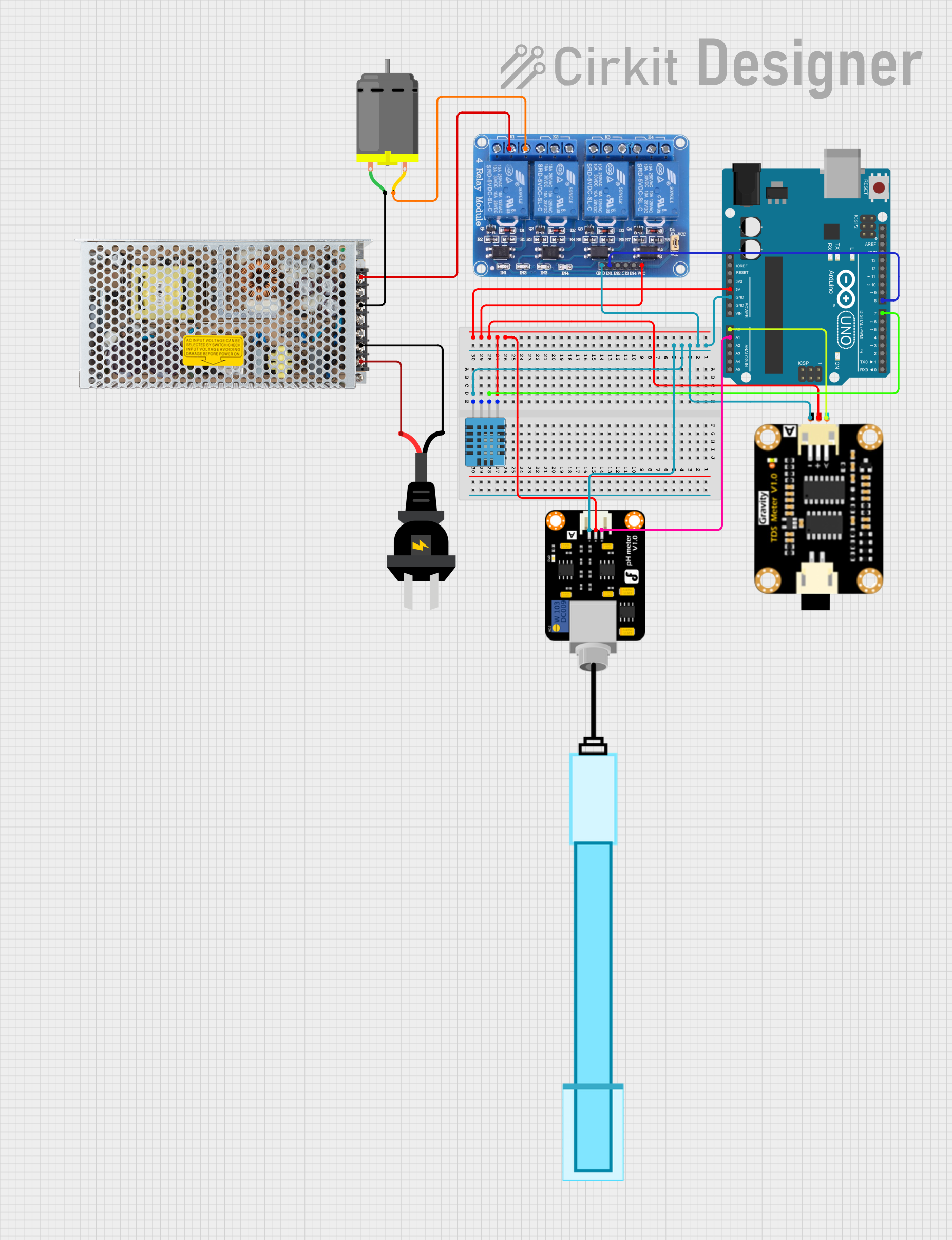
This circuit is designed to interface various sensors and actuators with an Arduino UNO microcontroller. It includes a DC motor controlled via a relay, a DHT11 humidity and temperature sensor, a TDS (Total Dissolved Solids) sensor module, a pH meter, and a switching power supply connected to an AC source. The Arduino UNO serves as the central processing unit, reading sensor data and controlling the DC motor through the relay.
Component List
DC Motor
- Description: A motor that converts DC electrical energy into mechanical energy.
- Pins: pin 1, pin 2
Relay 4 Channel 5v
- Description: An electrically operated switch that allows the Arduino to control higher power devices.
- Pins: GND, IN1, IN2, IN3, IN4, VCC, COM1, COM2, COM3, COM4, NO1, NO2, NO3, NO4, NC1, NC2, NC3, NC4
DHT11 Humidity and Temperature Sensor
- Description: A sensor that measures ambient humidity and temperature.
- Pins: VDD, DATA, NULL, GND
TDS Sensor Module
- Description: A sensor used to measure the total dissolved solids in water.
- Pins: TDS Negative, TDS Positive, TDS A
PH Meter
- Description: A sensor used to measure the acidity or alkalinity of a solution.
- Pins: Signal, VCC, GND
Switching Power Supply
- Description: A power supply that converts AC to DC power and regulates the output voltage.
- Pins: AC, GND, -V, +V
Arduino UNO
- Description: A microcontroller board based on the ATmega328P.
- Pins: UNUSED, IOREF, Reset, 3.3V, 5V, GND, Vin, A0-A5, SCL, SDA, AREF, D0-D13
AC Source
- Description: A source of alternating current (AC) electrical power.
- Pins: +, -
Wiring Details
DC Motor
- pin 1: Connected to the -V of the Switching Power Supply
- pin 2: Connected to the NO1 (Normally Open) contact of the Relay 4 Channel 5v
Relay 4 Channel 5v
- GND: Connected to GND of Arduino UNO
- IN1: Controlled by D8 of Arduino UNO
- VCC: Connected to 5V of Arduino UNO
- COM1: Connected to +V of the Switching Power Supply
- NO1: Connected to pin 2 of the DC Motor
DHT11 Humidity and Temperature Sensor
- VDD: Connected to 5V of Arduino UNO
- DATA: Connected to D7 of Arduino UNO
- GND: Connected to GND of Arduino UNO
TDS Sensor Module
- TDS Negative: Connected to GND of Arduino UNO
- TDS Positive: Connected to 5V of Arduino UNO
- TDS A: Connected to A0 of Arduino UNO
PH Meter
- Signal: Connected to A1 of Arduino UNO
- VCC: Connected to 5V of Arduino UNO
- GND: Connected to GND of Arduino UNO
Switching Power Supply
- AC: Connected to both + and - of the AC Source
- GND: Connected to pin 1 of the DC Motor
- -V: Connected to pin 1 of the DC Motor
- +V: Connected to COM1 of the Relay 4 Channel 5v
Arduino UNO
- 5V: Provides power to the Relay 4 Channel 5v, DHT11 Sensor, TDS Sensor Module, and PH Meter
- GND: Common ground for Relay 4 Channel 5v, DHT11 Sensor, TDS Sensor Module, and PH Meter
- D7: Reads data from the DHT11 Sensor
- D8: Controls IN1 of the Relay 4 Channel 5v
- A0: Reads analog data from the TDS Sensor Module
- A1: Reads analog data from the PH Meter
AC Source
- +: Connected to AC of the Switching Power Supply
- -: Connected to AC of the Switching Power Supply
Documented Code
Arduino UNO Code (sketch.ino)
void setup() {
  // put your setup code here, to run once:

}

void loop() {
  // put your main code here, to run repeatedly:

}
Note: The provided code is a template and does not include specific functionality. It needs to be completed with the logic for reading sensors and controlling the relay.