
Arduino-Controlled Robotic Vehicle with Bi-Directional DC Motors and LED Indicators
View and Edit Project In Cirkit Designer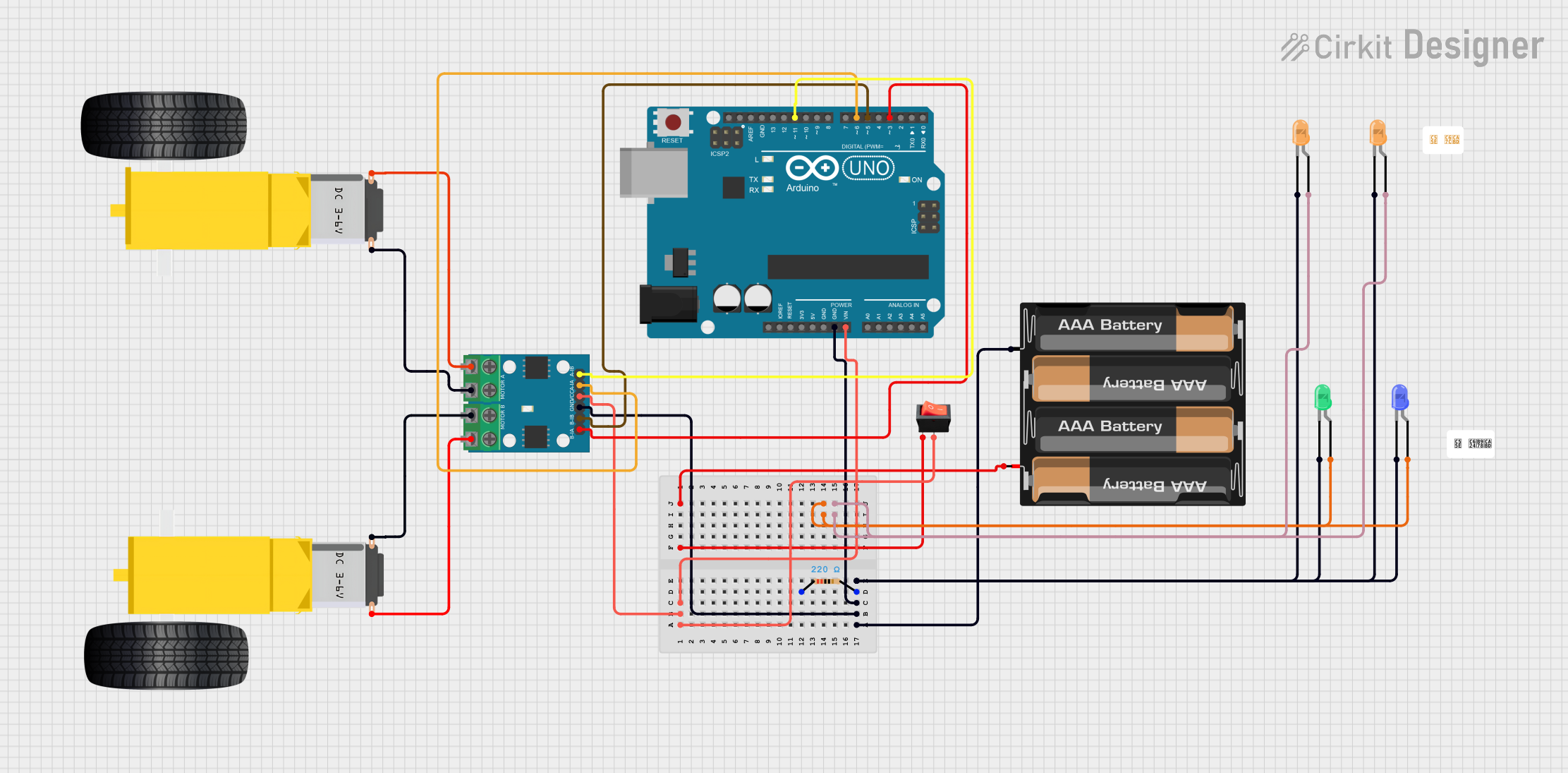
Circuit Documentation
Summary
This circuit appears to be designed for controlling a pair of gearmotors using an Arduino UNO and an L9110 motor driver. The circuit includes a power supply from a 4 x AAA battery mount, a rocker switch for power control, and several LEDs for indication purposes. The Arduino UNO is used as the central control unit, interfacing with the L9110 motor driver to control the speed and direction of the gearmotors. The LEDs are likely used as status indicators, and a resistor is included, possibly for current limiting to the blue LED.
Component List
Arduino UNO
- Microcontroller board based on the ATmega328P
- It has 14 digital input/output pins, 6 analog inputs, a 16 MHz quartz crystal, a USB connection, a power jack, an ICSP header, and a reset button.
Resistor (220 Ohms)
- A passive two-terminal electrical component that implements electrical resistance as a circuit element.
Gearmotor DC Wheels Right
- A DC gearmotor that is presumably used to drive the right wheel of a vehicle or robot.
Gearmotor DC Wheels Left
- A DC gearmotor that is presumably used to drive the left wheel of a vehicle or robot.
L9110 Motor Driver
- An integrated circuit designed to control motors with a wide range of voltages and currents; it can control two motors simultaneously.
Rocker Switch
- A switch that rocks back and forth, connecting either one of two circuits.
4 x AAA Battery Mount
- A battery holder for four AAA batteries, providing power to the circuit.
LED: Two Pin (Green, Blue, Orange)
- Light Emitting Diodes of different colors used for indication purposes.
Wiring Details
Arduino UNO
Vinconnected to the rocker switch (output) and L9110 (VCC)GNDconnected to the common ground netD11connected to L9110 (A-IB)D6connected to L9110 (A-IA)D5connected to L9110 (B-IB)D3connected to L9110 (B-IA)
Resistor (220 Ohms)
pin1not connectedpin2connected to the common ground net
Gearmotor DC Wheels Right
PIN1connected to L9110 (MOTOR B-B)PIN2connected to L9110 (MOTOR B-A)
Gearmotor DC Wheels Left
PIN1connected to L9110 (MOTOR A-B)PIN2connected to L9110 (MOTOR A-A)
L9110 Motor Driver
VCCconnected to the rocker switch (output)GNDconnected to the common ground netA-IA,A-IB,B-IA,B-IBconnected to respective Arduino UNO pinsMOTOR A-A,MOTOR A-Bconnected to Gearmotor DC Wheels LeftMOTOR B-A,MOTOR B-Bconnected to Gearmotor DC Wheels Right
Rocker Switch
inputconnected to the 4 x AAA Battery Mount (+)outputconnected to Arduino UNO (Vin) and L9110 (VCC)
4 x AAA Battery Mount
+connected to the rocker switch (input)-connected to the common ground net
LEDs (Green, Blue, Orange)
anodeof blue and green LEDs connected togetheranodeof orange LEDs connected togethercathodeof all LEDs connected to the common ground net
Documented Code
Arduino UNO (sketch.ino)
void setup() {
  // put your setup code here, to run once:

}

void loop() {
  // put your main code here, to run repeatedly:

}
Arduino UNO (documentation.txt)
(No additional documentation provided)
Please note that the code provided for the Arduino UNO is a template and does not contain any functional code to control the motors or LEDs. Additional code would be required to initialize the pins and implement the control logic for the motors and LEDs.