
Battery-Powered Transistor-Based Alarm Circuit with LED and Buzzer
View and Edit Project In Cirkit Designer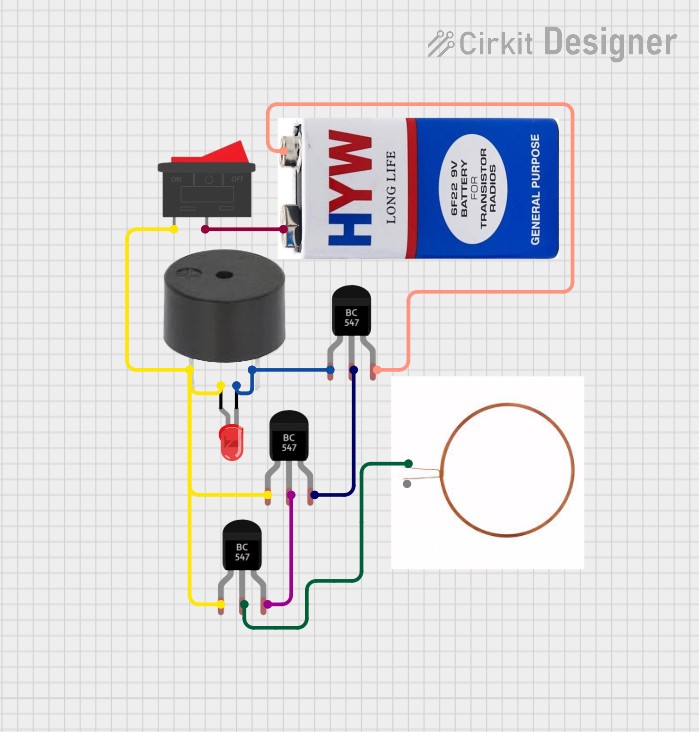
Circuit Documentation
Summary
This document provides a detailed overview of a circuit that includes transistors, a buzzer, an LED, a copper coil, a rocker switch, and a 9V battery. The circuit is designed to control the activation of the buzzer and LED through a series of interconnected transistors and a switch.
Component List
BC547 Transistor
- Description: NPN Bipolar Junction Transistor
- Pins: Collector, Base, Emitter
Buzzer
- Description: An electronic device that produces a sound
- Pins: PIN, GND
LED: Two Pin (red)
- Description: Light Emitting Diode
- Pins: Cathode, Anode
Copper Coil
- Description: Inductor used for electromagnetic applications
- Pins: -ve, +ve
Rocker Switch
- Description: A switch that rocks back and forth to open or close a circuit
- Pins: 1, 2
9V Battery
- Description: Power source for the circuit
- Pins: +, -
Wiring Details
BC547 Transistor 1
- Collector: Connected to Rocker Switch pin 1, BC547 Transistor 2 Collector, LED Anode, Buzzer PIN
- Base: Connected to BC547 Transistor 2 Emitter
- Emitter: Connected to BC547 Transistor 3 Base
BC547 Transistor 2
- Collector: Connected to Rocker Switch pin 1, BC547 Transistor 1 Collector, LED Anode, Buzzer PIN
- Base: Connected to Copper Coil -ve
- Emitter: Connected to BC547 Transistor 1 Base
BC547 Transistor 3
- Collector: Connected to LED Cathode, Buzzer GND
- Base: Connected to BC547 Transistor 1 Emitter
- Emitter: Connected to 9V Battery -
Buzzer
- PIN: Connected to Rocker Switch pin 1, BC547 Transistor 1 Collector, BC547 Transistor 2 Collector, LED Anode
- GND: Connected to BC547 Transistor 3 Collector
LED: Two Pin (red)
- Anode: Connected to Rocker Switch pin 1, BC547 Transistor 1 Collector, BC547 Transistor 2 Collector, Buzzer PIN
- Cathode: Connected to BC547 Transistor 3 Collector, Buzzer GND
Copper Coil
- -ve: Connected to BC547 Transistor 2 Base
- +ve: Not connected
Rocker Switch
- Pin 1: Connected to BC547 Transistor 1 Collector, BC547 Transistor 2 Collector, LED Anode, Buzzer PIN
- Pin 2: Connected to 9V Battery +
9V Battery
- -: Connected to BC547 Transistor 3 Emitter
- +: Connected to Rocker Switch pin 2
Code
There is no microcontroller code associated with this circuit.
This document provides a comprehensive overview of the circuit, including a summary, detailed component list, wiring details, and code documentation.