
Interactive LED Display with Dual Arduino Control and Encoder Input
View and Edit Project In Cirkit Designer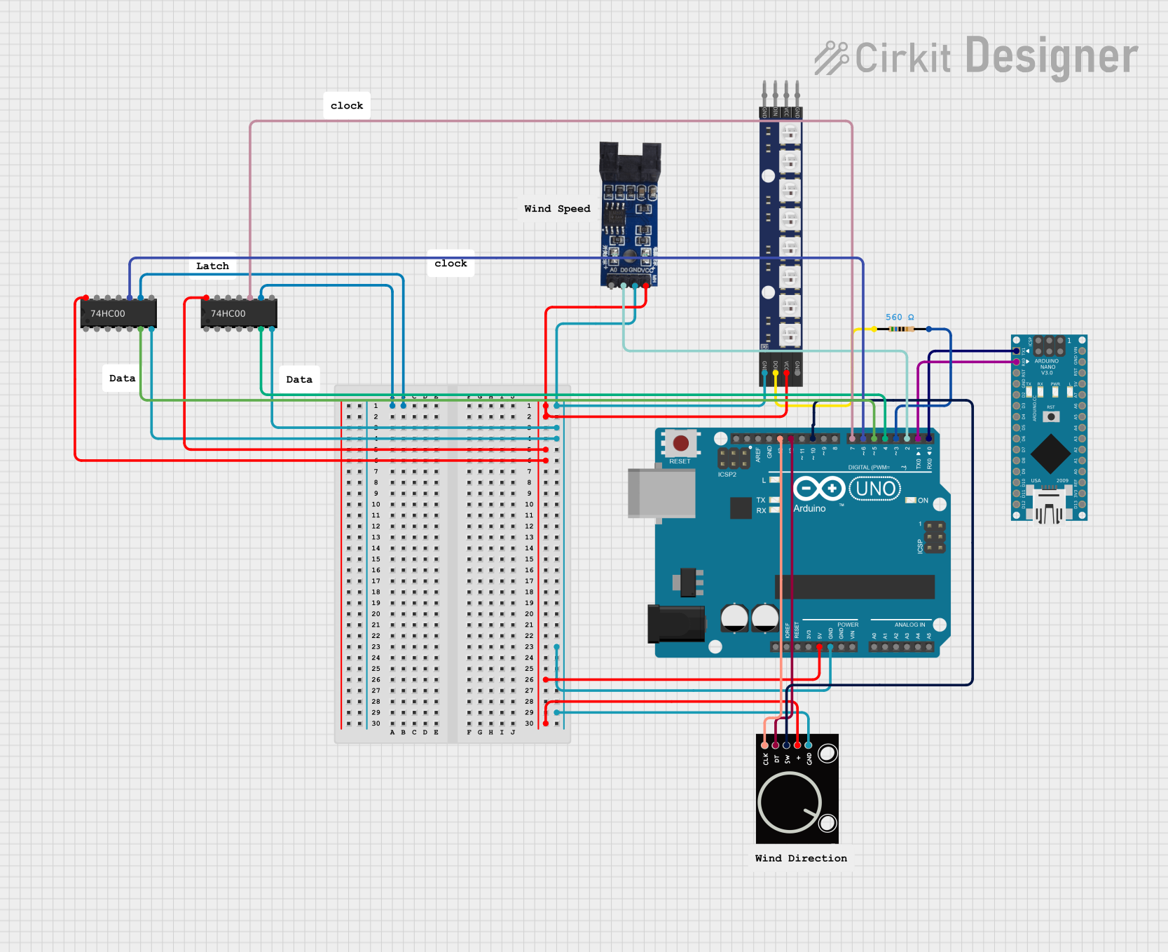
Circuit Documentation
Summary
This document provides a detailed overview of a circuit that includes a variety of components such as microcontrollers (Arduino UNO and Arduino Nano), logic gates (74HC00), a resistor, an RGB LED matrix, a rotary encoder, and an optical encoder sensor module. The circuit is designed to interface different sensors and actuators, with the Arduino UNO serving as the primary microcontroller. The Arduino Nano is included for additional functionality or processing. The 74HC00 logic gates are used for signal processing or control logic. The RGB LED matrix is controlled by the Arduino UNO, and the rotary encoder provides user input. The optical encoder sensor module is used for position or motion sensing.
Component List
Microcontrollers
- Arduino UNO: A microcontroller board based on the ATmega328P, featuring digital and analog I/O pins.
- Arduino Nano: A small, complete, and breadboard-friendly board based on the ATmega328P, similar to the Arduino UNO but in a smaller form factor.
Logic Gates
- 74HC00: A quad 2-input NAND gate IC used for creating complex logic circuits.
Passive Components
- Resistor: A passive two-terminal electrical component that implements electrical resistance as a circuit element. In this circuit, a 560 Ohm resistor is used.
Sensors and Actuators
- WS2812 RGB LED matrix 1x8: An 8-LED strip of individually addressable RGB LEDs.
- Rotary Encoder: An electro-mechanical device that converts the angular position or motion of a shaft or axle to an analog or digital signal.
- Optical Encoder Sensor Module: A sensor that provides feedback based on the movement detected by the optical encoder.
Wiring Details
Arduino UNO
- 5V connected to VCC of WS2812 RGB LED matrix, Optical Encoder Sensor Module, 74HC00 (both instances), and Rotary Encoder.
- GND connected to GND of WS2812 RGB LED matrix, Optical Encoder Sensor Module, 74HC00 (both instances), and Rotary Encoder.
- D13 connected to CLK of Rotary Encoder.
- D12 connected to DT of Rotary Encoder.
- D10 connected to SW of Rotary Encoder.
- D7 connected to 3B of 74HC00 (instance 1).
- D6 connected to 3B of 74HC00 (instance 2).
- D5 connected to 2Y of 74HC00 (instance 2).
- D4 connected to 2Y of 74HC00 (instance 1).
- D3 connected to pin2 of Resistor.
- D2 connected to D0 of Optical Encoder Sensor Module.
- D1 connected to D0/RX of Arduino Nano.
- D0 connected to D1/TX of Arduino Nano.
Arduino Nano
- D0/RX connected to D1 of Arduino UNO.
- D1/TX connected to D0 of Arduino UNO.
Resistor (560 Ohms)
- pin1 connected to DOUT of WS2812 RGB LED matrix.
- pin2 connected to D3 of Arduino UNO.
WS2812 RGB LED matrix 1x8
- VCC connected to 5V of Arduino UNO.
- GND connected to GND of Arduino UNO.
- DOUT connected to pin1 of Resistor.
Rotary Encoder
- + connected to 5V of Arduino UNO.
- GND connected to GND of Arduino UNO.
- SW connected to D10 of Arduino UNO.
- DT connected to D12 of Arduino UNO.
- CLK connected to D13 of Arduino UNO.
Optical Encoder Sensor Module
- VCC connected to 5V of Arduino UNO.
- GND connected to GND of Arduino UNO.
- D0 connected to D2 of Arduino UNO.
74HC00 (Instance 1 and Instance 2)
- 3A of both instances are interconnected.
- VCC connected to 5V of Arduino UNO.
- GND connected to GND of Arduino UNO.
- 3B of Instance 1 connected to D7 of Arduino UNO.
- 3B of Instance 2 connected to D6 of Arduino UNO.
- 2Y of Instance 1 connected to D4 of Arduino UNO.
- 2Y of Instance 2 connected to D5 of Arduino UNO.
Documented Code
Arduino UNO Code (sketch.ino)
void setup() {
  // put your setup code here, to run once:

}

void loop() {
  // put your main code here, to run repeatedly:

}
Arduino Nano Code (sketch.ino)
void setup() {
  // put your setup code here, to run once:

}

void loop() {
  // put your main code here, to run repeatedly:

}
Note: The actual functionality of the microcontrollers will be defined within the setup and loop functions of the Arduino code. The provided code snippets are templates and need to be filled with the logic specific to the application of the circuit.