Arduino Nano-Based Battery-Powered Smart Irrigation System with LCD Display
Circuit Documentation
Summary
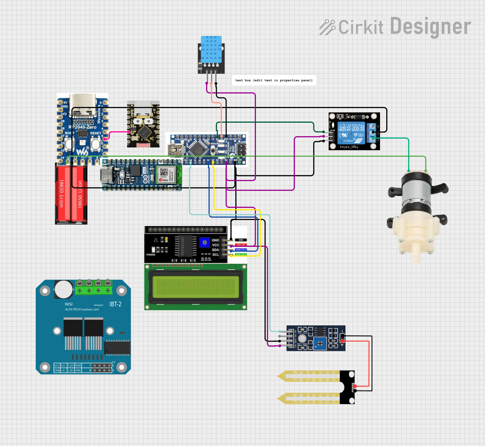
This circuit is designed to control a water pump based on soil moisture levels and display sensor data on an LCD. The main components include an Arduino Nano, a relay module, a DHT11 sensor, an LCD I2C display, a Humidity YL-69 sensor, a mini diaphragm water pump, and a 18650 Li-Ion battery. The Arduino Nano reads data from the DHT11 and Humidity YL-69 sensors, displays the data on the LCD, and controls the water pump via the relay module.
Component List
Arduino Nano
- Description: Microcontroller board based on the ATmega328P.
- Pins: D12, D11, D10, D9, D8, D7, D6, D5, D4, D3, D2, GND, RST, RX0, TX1, D13, 3V3, REF, A0, A1, A3, A4, A5, A6, A7, 5V, VIN
Relay module 1 channel
- Description: Relay module for switching high-power devices.
- Pins: S, 5V, GND, NC, COM, NO
DHT11
- Description: Humidity and temperature sensor.
- Pins: 5V, S, GND
LCD I2C Display
- Description: 16x2 character LCD with I2C interface.
- Pins: GND, VCC, SDA, SCL
Humidity YL-69
- Description: Soil moisture sensor.
- Pins: A0, D0, GND, VCC
Mini Diaphragm Water Pump
- Description: Small water pump for liquid transfer.
- Pins: Positive (+), Negative (-)
18650 Li-Ion
- Description: Rechargeable lithium-ion battery.
- Pins: Positive, Negative
rp2040 zero
- Description: Microcontroller board based on the RP2040.
- Pins: 5V, GND, 3V3, 29, 28, 27, 26, 15, 14, 13, 12, 11, 10, 9, 8, 7, 6, 5, 4, 3, 2, 1, 0
ESP32C3 Supermini
- Description: Microcontroller board based on the ESP32-C3.
- Pins: GPIO05, GPIO06, GPIO07, GPIO08, GPIO09, GPIO10, GPIO20, GPIO21, GPIO00, GPIO01, GPIO02, GPIO03, GPIO04, 3.3V, GND, +5V
Arduino Nano ESP32
- Description: Microcontroller board based on the ESP32.
- Pins: D12, D11, D10, D9, D8, D7, D6, D5, D4, D3, D2, GND, RST, RX0, TX1, D13, 3.3V, B0, A0, A1, A2, A3, A4, A5, A6, A7, VBUS, B1, VIN
Wiring Details
Arduino Nano
- D3 connected to Relay module 1 channel (S)
- D2 connected to DHT11 (S)
- GND connected to DHT11 (GND)
- A0 connected to Humidity YL-69 (A0)
- A4 connected to LCD I2C Display (SDA)
- A5 connected to LCD I2C Display (SCL)
- 5V connected to:
- Relay module 1 channel (5V)
- DHT11 (5V)
- Humidity YL-69 (VCC)
- LCD I2C Display (VCC)
- GND connected to:
- Relay module 1 channel (GND)
- Relay module 1 channel (COM)
- Humidity YL-69 (GND)
- 18650 Li-Ion (Negative)
- LCD I2C Display (GND)
- VIN connected to:
- 18650 Li-Ion (Positive)
- Mini Diaphragm Water Pump (Positive (+))
Relay module 1 channel
- S connected to Arduino Nano (D3)
- 5V connected to Arduino Nano (5V)
- GND connected to Arduino Nano (GND)
- COM connected to Arduino Nano (GND)
- NO connected to Mini Diaphragm Water Pump (Negative (-))
DHT11
- S connected to Arduino Nano (D2)
- GND connected to Arduino Nano (GND)
- 5V connected to Arduino Nano (5V)
LCD I2C Display
- SDA connected to Arduino Nano (A4)
- SCL connected to Arduino Nano (A5)
- VCC connected to Arduino Nano (5V)
- GND connected to Arduino Nano (GND)
Humidity YL-69
- A0 connected to Arduino Nano (A0)
- VCC connected to Arduino Nano (5V)
- GND connected to Arduino Nano (GND)
Mini Diaphragm Water Pump
- Positive (+) connected to Arduino Nano (VIN)
- Negative (-) connected to Relay module 1 channel (NO)
18650 Li-Ion
- Positive connected to Arduino Nano (VIN)
- Negative connected to Arduino Nano (GND)
rp2040 zero
- Pin 5 connected to ESP32C3 Supermini (GPIO10)
Code Documentation
/*
 * Arduino Sketch for controlling a water pump based on humidity levels
 * and displaying sensor data on an LCD.
 *
 * Components:
 * - Arduino Nano
 * - Relay module 1 channel
 * - DHT11 sensor
 * - LCD I2C Display
 * - Humidity YL-69 sensor
 * - Mini Diaphragm Water Pump
 * - 18650 Li-Ion battery
 */

#include <Wire.h>
#include <LiquidCrystal_I2C.h>
#include <DHT.h>

// Pin definitions
#define DHTPIN 2
#define RELAY_PIN 3
#define HUMIDITY_SENSOR_PIN A0

// DHT sensor type
#define DHTTYPE DHT11

// Initialize DHT sensor
DHT dht(DHTPIN, DHTTYPE);

// Initialize LCD
LiquidCrystal_I2C lcd(0x27, 16, 2);

void setup() {
  // Start serial communication
  Serial.begin(9600);

  // Initialize DHT sensor
  dht.begin();

  // Initialize LCD
  lcd.init();
  lcd.backlight();

  // Set relay pin as output
  pinMode(RELAY_PIN, OUTPUT);

  // Set initial state of relay
  digitalWrite(RELAY_PIN, LOW);
}

void loop() {
  // Read humidity and temperature from DHT11
  float humidity = dht.readHumidity();
  float temperature = dht.readTemperature();

  // Read soil moisture level
  int soilMoisture = analogRead(HUMIDITY_SENSOR_PIN);

  // Display data on LCD
  lcd.setCursor(0, 0);
  lcd.print("Temp: ");
  lcd.print(temperature);
  lcd.print(" C");
  lcd.setCursor(0, 1);
  lcd.print("Humidity: ");
  lcd.print(humidity);
  lcd.print(" %");

  // Control relay based on soil moisture level
  if (soilMoisture < 500) { // Adjust threshold as needed
    digitalWrite(RELAY_PIN, HIGH); // Turn on pump
  } else {
    digitalWrite(RELAY_PIN, LOW); // Turn off pump
  }

  // Print data to serial monitor
  Serial.print("Temperature: ");
  Serial.print(temperature);
  Serial.print(" C, Humidity: ");
  Serial.print(humidity);
  Serial.print(" %, Soil Moisture: ");
  Serial.println(soilMoisture);

  // Wait before next loop
  delay(2000);
}
This code initializes the DHT11 sensor and LCD, reads humidity and temperature data from the DHT11, reads soil moisture levels from the Humidity YL-69 sensor, displays the data on the LCD, and controls the water pump via the relay module based on the soil moisture levels. The data is also printed to the serial monitor for debugging purposes.