
Arduino Mega 2560 Environmental Control System with DHT11 Sensor and I2C LCD
View and Edit Project In Cirkit Designer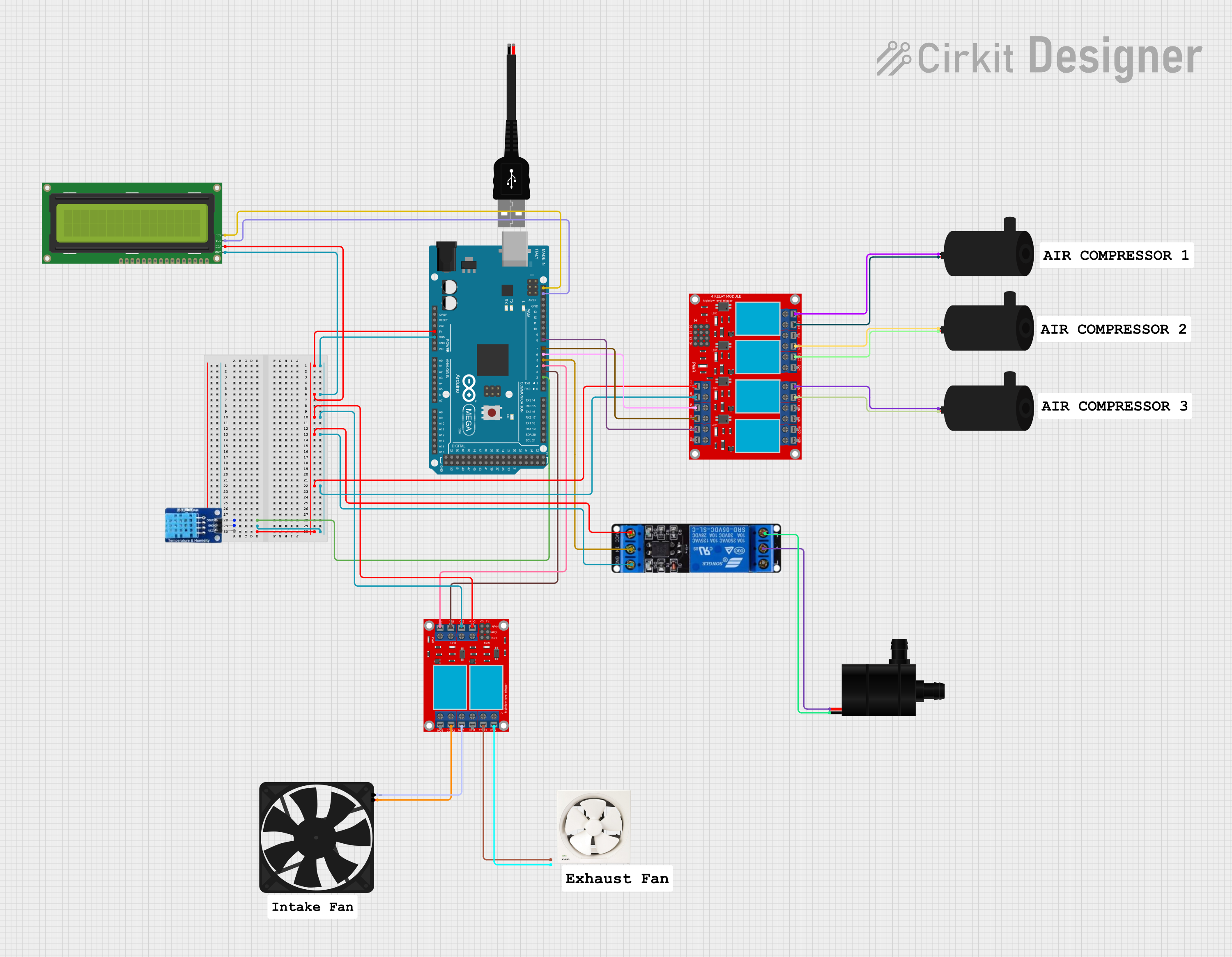
Circuit Documentation
Summary
This circuit is an environmental control system that monitors temperature and humidity using a DHT11 sensor and controls various devices such as an exhaust fan, intake fan, sprinkler, and compressors. The system is managed by an Arduino Mega 2560 microcontroller, which also displays the current temperature and humidity on a 16x2 I2C LCD. The exhaust fan activates when the temperature exceeds a set range, followed by the intake fan after 20 seconds. The sprinkler activates when humidity falls below a set range. The compressors operate on specific schedules and durations.
Component List
Exhaust Fan 12"
- Pins: Live, Neutral
- Description: Controls air exhaust based on temperature.
Fan
- Pins: GND, 5V
- Description: Controls air intake based on temperature.
DHT11
- Pins: DATA, GND, VCC
- Description: Measures temperature and humidity.
16x2 I2C LCD
- Pins: GND, VCC, SDA, SCL
- Description: Displays temperature and humidity readings.
Arduino Mega 2560
- Pins: IOREF, RESET, 3V3, 5V, GND, VIN, A0-A15, D0-D53, SDA, SCL, AREF
- Description: Microcontroller that manages the entire system.
2 Channel Relay Module
- Pins: N.O. 2, COM 2, N.C. 2, N.O. 1, COM 1, N.C. 1, pin 7-12, VCC+, VCC- (GND), IN 1, IN 2
- Description: Controls the exhaust fan and intake fan.
Water Pump
- Pins: VCC, GND
- Description: Activates based on humidity levels.
Relay 12V
- Pins: ground, in, VCC, NO, COM, NC
- Description: Controls the water pump.
4 Channel Relay Module
- Pins: N.O. 4, COM 4, N.C. 4, N.O. 3, COM 3, N.C. 3, N.O. 2, COM 2, N.C. 2, N.O. 1, COM 1, N.C. 1, Pin 13-24, VCC+, VCC- (GND), IN 1-4
- Description: Controls the compressors.
USB Male 2 Pin Connection
- Pins: Negative -, Positive +
- Description: Provides power to the circuit.
Wiring Details
Exhaust Fan 12"
- Live connected to COM 1 of the 2 Channel Relay Module.
- Neutral connected to N.C. 1 of the 2 Channel Relay Module.
Fan
- GND connected to N.C. 2 of the 2 Channel Relay Module.
- 5V connected to COM 2 of the 2 Channel Relay Module.
DHT11
- DATA connected to D2 PWM of the Arduino Mega 2560.
- GND connected to GND of the Arduino Mega 2560.
- VCC connected to 5V of the Arduino Mega 2560.
16x2 I2C LCD
- GND connected to GND of the Arduino Mega 2560.
- VCC connected to 5V of the Arduino Mega 2560.
- SDA connected to SDA of the Arduino Mega 2560.
- SCL connected to SCL of the Arduino Mega 2560.
Arduino Mega 2560
- D2 PWM connected to DATA of the DHT11.
- GND connected to GND of the DHT11, 16x2 I2C LCD, 2 Channel Relay Module, Relay 12V, and 4 Channel Relay Module.
- 5V connected to VCC of the DHT11, 16x2 I2C LCD, 2 Channel Relay Module, Relay 12V, and 4 Channel Relay Module.
- D3 PWM connected to IN 1 of the 2 Channel Relay Module.
- D4 PWM connected to IN 2 of the 2 Channel Relay Module.
- D5 PWM connected to in of the Relay 12V.
- D6 PWM connected to IN 1 of the 4 Channel Relay Module.
- D7 PWM connected to IN 2 of the 4 Channel Relay Module.
- D8 PWM connected to IN 3 of the 4 Channel Relay Module.
- SDA connected to SDA of the 16x2 I2C LCD.
- SCL connected to SCL of the 16x2 I2C LCD.
2 Channel Relay Module
- N.C. 2 connected to GND of the Fan.
- COM 2 connected to 5V of the Fan.
- COM 1 connected to Live of the Exhaust Fan 12".
- N.C. 1 connected to Neutral of the Exhaust Fan 12".
- IN 1 connected to D3 PWM of the Arduino Mega 2560.
- IN 2 connected to D4 PWM of the Arduino Mega 2560.
Water Pump
- VCC connected to COM of the Relay 12V.
- GND connected to NC of the Relay 12V.
Relay 12V
- ground connected to GND of the Arduino Mega 2560.
- in connected to D5 PWM of the Arduino Mega 2560.
- VCC connected to 5V of the Arduino Mega 2560.
- COM connected to VCC of the Water Pump.
- NC connected to GND of the Water Pump.
4 Channel Relay Module
- COM 1 connected to positive of the Water Pump.
- N.C. 1 connected to negative of the Water Pump.
- COM 2 connected to positive of the Water Pump.
- N.C. 2 connected to negative of the Water Pump.
- COM 3 connected to positive of the Water Pump.
- N.C. 3 connected to negative of the Water Pump.
- IN 1 connected to D6 PWM of the Arduino Mega 2560.
- IN 2 connected to D7 PWM of the Arduino Mega 2560.
- IN 3 connected to D8 PWM of the Arduino Mega 2560.
Code Documentation
/*
 * This Arduino sketch controls an environmental system based on temperature and
 * humidity readings from a DHT11 sensor. The system includes an exhaust fan,
 * intake fan, sprinkler, and three compressors. The exhaust fan activates when
 * the temperature exceeds a set range, followed by the intake fan after 20
 * seconds. The sprinkler activates when humidity falls below a set range. The
 * compressors operate on specific schedules and durations. The current
 * temperature and humidity are displayed on a 16x2 I2C LCD.
 */

#include <Wire.h>
#include <LiquidCrystal_I2C.h>
#include <DHT.h>

#define DHTPIN 2
#define DHTTYPE DHT11
#define EXHAUST_FAN_PIN 3
#define INTAKE_FAN_PIN 4
#define SPRINKLER_PIN 5
#define COMPRESSOR1_PIN 6
#define COMPRESSOR2_PIN 7
#define COMPRESSOR3_PIN 8

DHT dht(DHTPIN, DHTTYPE);
LiquidCrystal_I2C lcd(0x27, 16, 2);

const float TEMP_MIN = 30.0;
const float TEMP_MAX = 36.0;
const float HUMIDITY_MIN = 85.0;
const float HUMIDITY_MAX = 95.0;

void setup() {
  pinMode(EXHAUST_FAN_PIN, OUTPUT);
  pinMode(INTAKE_FAN_PIN, OUTPUT);
  pinMode(SPRINKLER_PIN, OUTPUT);
  pinMode(COMPRESSOR1_PIN, OUTPUT);
  pinMode(COMPRESSOR2_PIN, OUTPUT);
  pinMode(COMPRESSOR3_PIN, OUTPUT);
  lcd.begin();
  lcd.backlight();
  dht.begin();
}

void loop() {
  float temp = dht.readTemperature();
  float humidity = dht.readHumidity();

  lcd.setCursor(0, 0);
  lcd.print("Temp: ");
  lcd.print(temp);
  lcd.print("C");
  lcd.setCursor(0, 1);
  lcd.print("Humidity: ");
  lcd.print(humidity);
  lcd.print("%");

  if (temp > TEMP_MAX) {