Cirkit Designer
Your all-in-one circuit design IDE
Home /
Project Documentation
Arduino and ESP8266 Nodemcu Controlled Robotic Vehicle with RFID and Ultrasonic Sensing

Circuit Documentation
Summary
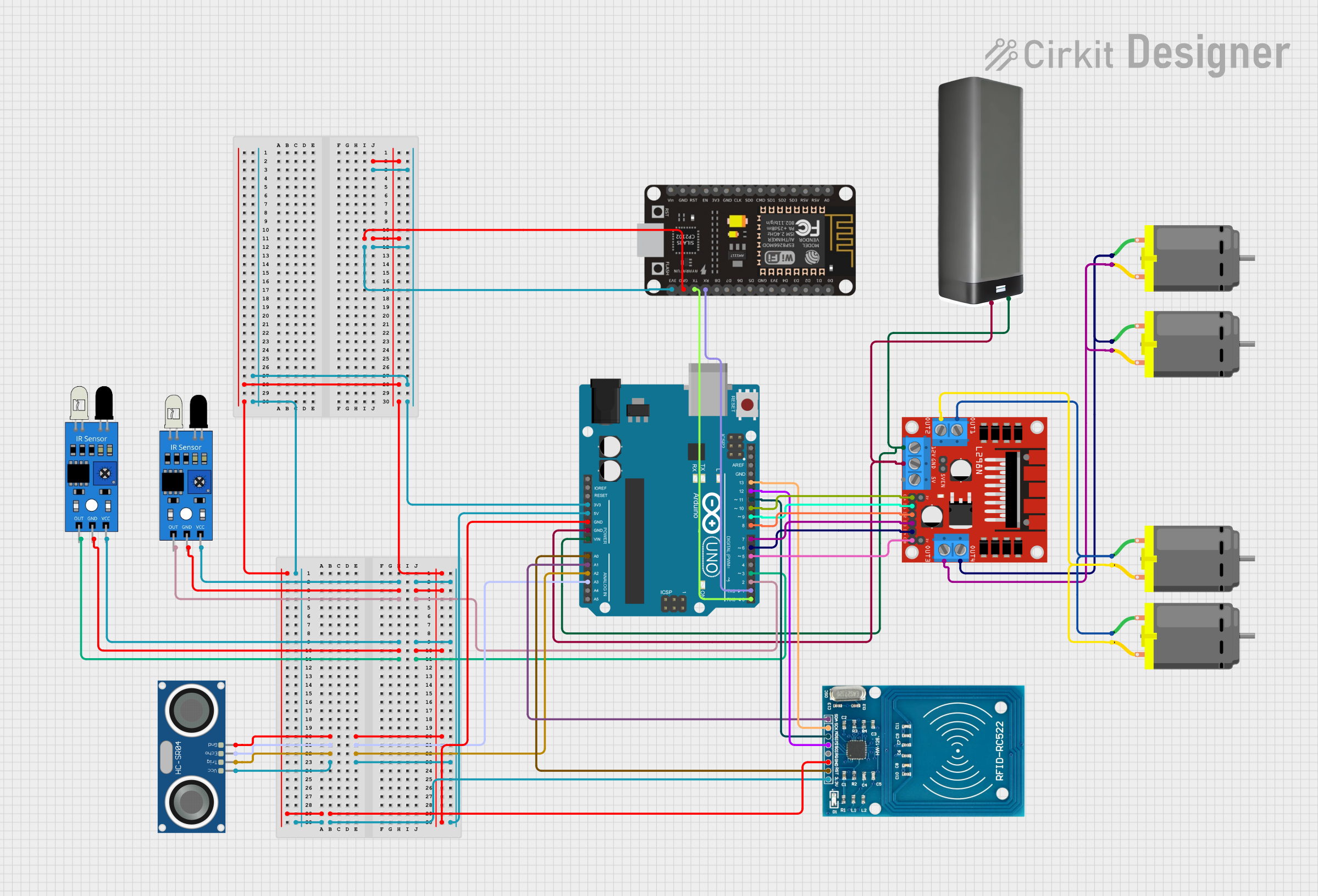
The circuit in question appears to be a robotic control system utilizing an Arduino UNO as the primary microcontroller, interfaced with various sensors and actuators. The system includes IR sensors for object detection, an HC-SR04 ultrasonic sensor for distance measurement, an RFID-RC522 module for identification tasks, and an ESP8266 NodeMCU for wireless communication capabilities. The circuit also includes a motor driver (L298N) to control multiple DC motors, which likely serve as the actuators for the robot's movement. A battery pack provides the power source for the system.
Component List
Microcontrollers
- Arduino UNO: A microcontroller board based on the ATmega328P, featuring digital and analog I/O pins.
- ESP8266 NodeMCU: A Wi-Fi enabled microcontroller module based on the ESP8266 chip, suitable for IoT applications.
Sensors
- IR Sensors: Used for object detection or line tracking.
- HC-SR04 Ultrasonic Sensor: Measures distances using ultrasonic waves.
- RFID-RC522: An RFID reader module for reading RFID tags.
Actuators
- DC Motors: Actuators that convert electrical energy into mechanical motion.
- L298N DC Motor Driver: A module that allows control of high current DC motors.
Power Supply
- Battery Pack: Provides the necessary voltage and current to power the circuit.
Wiring Details
Arduino UNO
- 5V: Connected to the VCC pins of IR sensors and the HC-SR04 ultrasonic sensor.
- GND: Common ground for IR sensors, HC-SR04, ESP8266 NodeMCU, RFID-RC522, and L298N motor driver.
- Digital Pins (D0-D13): Various connections to the IR sensors, motor driver, and RFID-RC522 for control signals.
- Analog Pins (A0-A5): Connected to the RFID-RC522 and HC-SR04 for data communication.
- Vin: Receives power from the battery pack.
- Reset, IOREF, AREF: Unused in this circuit.
IR Sensors
- VCC: Powered by the Arduino's 5V output.
- GND: Connected to the Arduino's ground.
- Out: Output signal connected to the Arduino's digital pins (D2, D3).
HC-SR04 Ultrasonic Sensor
- VCC: Powered by the Arduino's 5V output.
- GND: Connected to the Arduino's ground.
- ECHO: Connected to the Arduino's analog pin (A3).
- TRIG: Connected to the Arduino's analog pin (A2).
RFID-RC522
- VCC (3.3V): Powered by the Arduino's 3.3V output.
- RST: Connected to the Arduino's analog pin (A0).
- GND: Connected to the Arduino's ground.
- IRQ: Not connected in this circuit.
- MISO, MOSI, SCK, SDA: Connected to the Arduino's digital pins (D12, D11, D13, A1) for SPI communication.
L298N DC Motor Driver
- 12V: Powered by the battery pack.
- GND: Connected to the Arduino's ground.
- 5V: Not used in this circuit.
- Motor Outputs (OUT1-OUT4): Connected to the DC motors.
- Control Inputs (ENA, ENB, IN1-IN4): Connected to the Arduino's digital pins (D10, D5, D9, D8, D7, D6) for motor control.
ESP8266 NodeMCU
- 3V3: Powered by the Arduino's 3.3V output.
- GND: Connected to the Arduino's ground.
- RX, TX: Connected to the Arduino's digital pins (D1, D0) for serial communication.
DC Motors
- Pin 1 and Pin 2: Connected to the L298N motor driver outputs.
Battery Pack
- +: Connected to the Arduino's Vin and the L298N motor driver's 12V input.
- -: Connected to the Arduino's ground.
Documented Code
Arduino UNO Code
#include <SPI.h>
#include <MFRC522.h>

// Define sensor pins
const int leftSensorPin = 2;
const int rightSensorPin = 3;
const int trigPin = 16;
const int echoPin = 17;

// Define motor pins
const int motor1Enable = 10;
const int motor1In1 = 9;
const int motor1In2 = 8;
const int motor2In3 = 7;
const int motor2In4 = 6;
const int motor2Enable = 5;
// Define RFID pins
#define RST_PIN 14
#define SS_PIN 15

MFRC522 mfrc522(SS_PIN, RST_PIN);  // Create instance of the RFID reader

bool manualMode = false; // Flag for manual mode

void setup() {
  // Initialize motor pins
  pinMode(motor1Enable, OUTPUT);
  pinMode(motor1In1, OUTPUT);
  pinMode(motor1In2, OUTPUT);
  pinMode(motor2Enable, OUTPUT);
  pinMode(motor2In3, OUTPUT);
  pinMode(motor2In4, OUTPUT);

  // Initialize sensor pins
  pinMode(leftSensorPin, INPUT);
  pinMode(rightSensorPin, INPUT);
  pinMode(trigPin, OUTPUT);
  pinMode(echoPin, INPUT);

  // RFID initialization
  SPI.begin();        // Start SPI communication
  mfrc522.PCD_Init(); // Init MFRC522 module

  Serial.begin(9600);  // For debugging
}

// ... (rest of the code)
ESP8266 NodeMCU Code
#include <ESP8266WiFi.h>
#include <BlynkSimpleEsp8266.h>
#include <Servo.h>

#define BLYNK_TEMPLATE_ID "YourTemplateID"
#define BLYNK_DEVICE_NAME "YourDeviceName"
#define BLYNK_AUTH_TOKEN "YourAuthToken"

char auth[] = BLYNK_AUTH_TOKEN;
char ssid[] = "YourSSID";
char pass[] = "YourPassword";

// Virtual pins for manual control
#define VPIN_FORWARD V1
#define VPIN_BACKWARD V2
#define VPIN_LEFT V3
#define VPIN_RIGHT V4
#define VPIN_STOP V5
#define VPIN_MODE V6

bool manualMode = false;

BLYNK_WRITE(VPIN_FORWARD) {
    if (manualMode && param.asInt() == 1) {
        Serial.write('F');
    }
}

// ... (rest of the code)
(Note: The rest of the code is omitted for brevity. The provided code snippets are the initial parts of the full code for each microcontroller.)