
Arduino Uno R3 Based Health Monitoring and GPS Tracking System
View and Edit Project In Cirkit Designer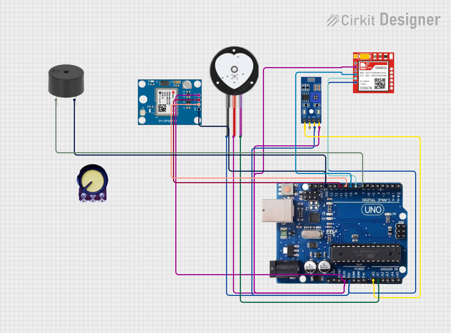
Circuit Documentation
Summary
This circuit is designed to monitor environmental sound levels and heart rate, and to send GPS location data via GSM when certain thresholds are exceeded. It utilizes an Arduino Uno R3 as the central microcontroller to interface with a sound level sensor (LM393), a heart pulse sensor, a Neo 6M GPS module, a Sim800l GSM module, and a buzzer for alerts. The Arduino Uno R3 is programmed to read the analog values from the sensors, compare them against predefined thresholds, and trigger the buzzer if the conditions are met. Additionally, it sends the GPS location through the GSM module as an SMS message in case of an alert.
Component List
Arduino Uno R3
- Microcontroller board based on the ATmega328P
- Features digital I/O pins, analog input pins, and various power options
LM393
- Dual differential comparator that provides a digital signal representing sound levels
Neo 6M GPS Module
- Satellite navigation module capable of providing geographic coordinates
Potentiometer
- Variable resistor used to adjust a voltage level
Heart Pulse Sensor
- Optical heart rate sensor designed for measuring pulse rates
Sim800l
- GSM/GPRS module for cellular communication, capable of sending SMS and making calls
Buzzer
- An electromechanical component that emits sound when an electrical signal is applied
Wiring Details
Arduino Uno R3
5Vconnected to VCC of Sim800l, Heart Pulse Sensor, LM393, and Neo 6M GPS ModuleGNDconnected to GND of Sim800l, Heart Pulse Sensor, LM393, Neo 6M GPS Module, and BuzzerA0connected to A0 of LM393 (Sound Level)A1connected to SIGNAL of Heart Pulse SensorD7connected to PIN of BuzzerD8connected to TXD of Sim800l (GSM Module)D9connected to RXD of Sim800l (GSM Module)D10connected to RX of Neo 6M GPS ModuleD11connected to TX of Neo 6M GPS Module
LM393
A0connected to A0 of Arduino Uno R3D0not connectedGNDconnected to GND of Arduino Uno R3VCCconnected to 5V of Arduino Uno R3
Neo 6M GPS Module
GNDconnected to GND of Arduino Uno R3TXconnected to D11 of Arduino Uno R3RXconnected to D10 of Arduino Uno R3VCCconnected to 5V of Arduino Uno R3
Potentiometer
- Not connected in this circuit
Heart Pulse Sensor
GNDconnected to GND of Arduino Uno R3VCCconnected to 5V of Arduino Uno R3SIGNALconnected to A1 of Arduino Uno R3
Sim800l
NETnot connectedRSTnot connectedVCCconnected to 5V of Arduino Uno R3RXDconnected to D9 of Arduino Uno R3TXDconnected to D8 of Arduino Uno R3GNDconnected to GND of Arduino Uno R3
Buzzer
PINconnected to D7 of Arduino Uno R3GNDconnected to GND of Arduino Uno R3
Documented Code
#include <SoftwareSerial.h>

const int soundPin = A0;  // LM393 Analog Output
const int heartRatePin = A1;
const int buzzerPin = 7;

const int gpsRxPin = 10;
const int gpsTxPin = 11;
const int gsmRxPin = 8;
const int gsmTxPin = 9;

SoftwareSerial gpsSerial(gpsRxPin, gpsTxPin); // RX, TX for GPS
SoftwareSerial gsmSerial(gsmRxPin, gsmTxPin); // RX, TX for GSM

const int soundThreshold = 500;
const int heartRateThreshold = 600;

void setup() {
  pinMode(soundPin, INPUT);
  pinMode(heartRatePin, INPUT);
  pinMode(buzzerPin, OUTPUT);

  Serial.begin(9600);
  gpsSerial.begin(9600);  // GPS baud rate
  gsmSerial.begin(9600);  // GSM baud rate

  Serial.println("System Initialized");
}

void loop() {
  int soundLevel = analogRead(soundPin);
  int heartRate = analogRead(heartRatePin);

  Serial.print("Sound Level: ");
  Serial.println(soundLevel);
  Serial.print("Heart Rate: ");
  Serial.println(heartRate);

  if (soundLevel > soundThreshold || heartRate > heartRateThreshold) {
    digitalWrite(buzzerPin, HIGH);  // Activate buzzer
    Serial.println("Danger detected! Buzzer ON.");
    sendGPSLocation();
  } else {
    digitalWrite(buzzerPin, LOW);   // Deactivate buzzer
    Serial.println("Safe. Buzzer OFF.");
  }

  delay(1000);
}

void sendGPSLocation() {
  gsmSerial.println("AT"); // Check connection
  delay(1000);
  gsmSerial.println("AT+CMGF=1"); // Set SMS mode to text
  delay(1000);
  gsmSerial.println("AT+CMGS=\"+1234567890\""); // Recipient phone number
  delay(1000);

  gsmSerial.println("Danger detected. GPS Location:");

  while (gpsSerial.available()) {
    char c = gpsSerial.read();
    gsmSerial.write(c); // Send GPS data to GSM
  }

  delay(1000);
  gsmSerial.println((char)26); // End SMS with Ctrl+Z

  Serial.println("SMS sent with GPS location.");
}
This code is designed to run on the Arduino Uno R3. It initializes the serial communications for both the GPS and GSM modules, reads the sound level and heart rate, and triggers the buzzer if the readings exceed the set thresholds. It also contains a function sendGPSLocation to send the current GPS location via SMS using the GSM module.