Cirkit Designer
Your all-in-one circuit design IDE
Home /
Project Documentation
Arduino Mega 2560 Controlled Relay and Servo Automation System

Circuit Documentation
Summary
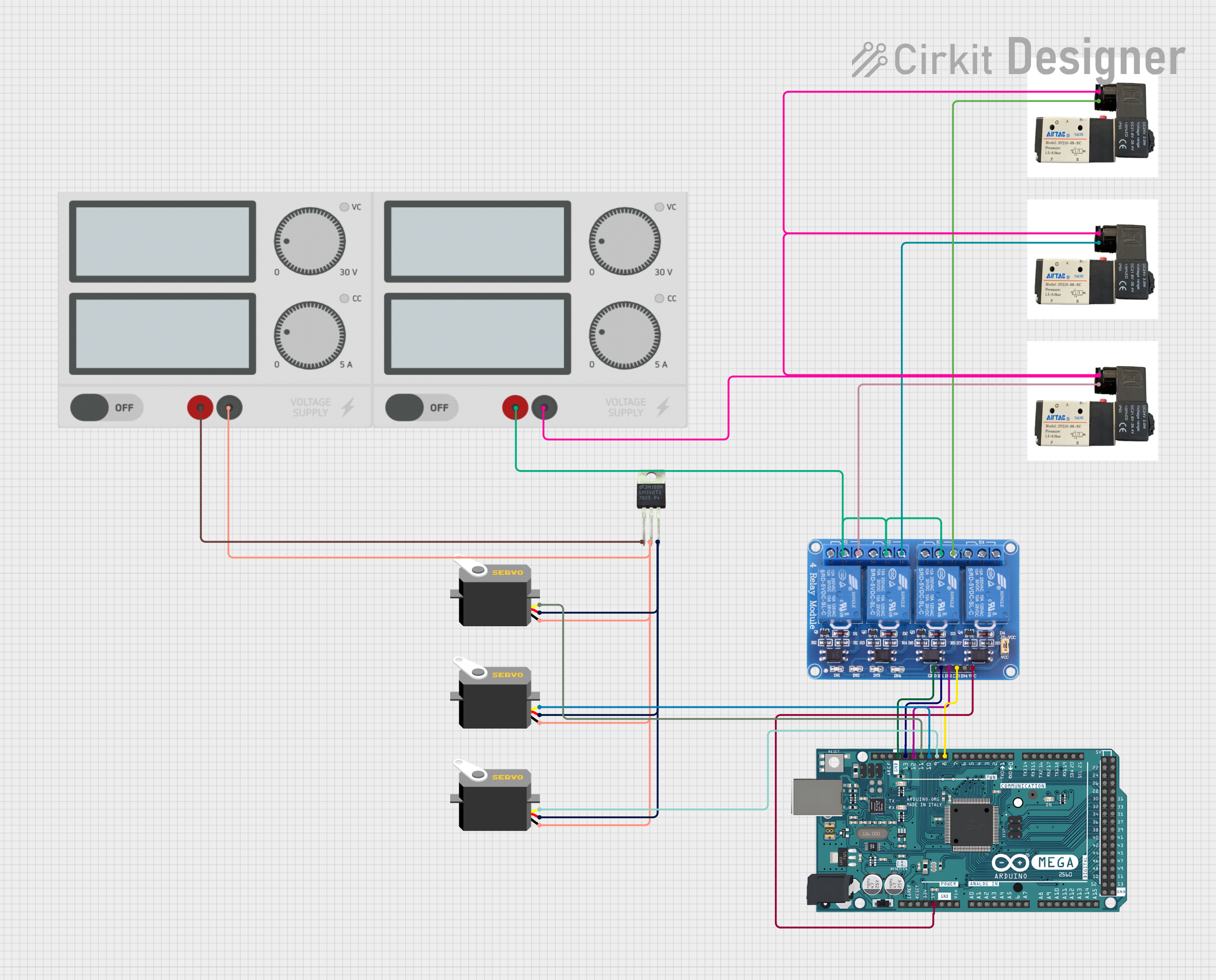
This circuit is designed to control a set of pneumatic solenoid valves and servos using an Arduino Mega 2560 microcontroller. The circuit includes a 4-channel relay module to switch the solenoid valves and a voltage regulator to supply the servos. The power supply provides the necessary voltage and current to the system.
Component List
Arduino Mega 2560
- Microcontroller board based on the ATmega2560
- It has 54 digital input/output pins (of which 15 can be used as PWM outputs), 16 analog inputs, 4 UARTs (hardware serial ports), a 16 MHz crystal oscillator, a USB connection, a power jack, an ICSP header, and a reset button.
Relay 4 Channel 5v
- A 4-channel relay module with 5V operating voltage
- It can be used to control various appliances and other equipment with large current.
Servo (3 instances)
- A rotary actuator or linear actuator that allows for precise control of angular or linear position, velocity, and acceleration.
- It consists of a suitable motor coupled to a sensor for position feedback.
LM340T5 7805
- A voltage regulator that outputs a fixed 5V from a higher voltage input.
Pneumatic Solenoid Valve (3 instances)
- An electromechanically operated valve controlled by an electric current through a solenoid.
- Used to control the flow of air in pneumatic systems.
Power Supply (2 instances)
- Provides the required electrical power to the circuit.
- It has a positive (+) and negative (-) terminal for DC power output.
Wiring Details
Arduino Mega 2560
5Vconnected to Relay 4 Channel 5vVCCD8 PWMconnected to Relay 4 Channel 5vIN3D9 PWMconnected to ServopulseD10 PWMconnected to ServopulseD11 PWMconnected to ServopulseD12 PWMconnected to Relay 4 Channel 5vIN2D13 PWMconnected to Relay 4 Channel 5vIN1GNDconnected to Relay 4 Channel 5vGND
Relay 4 Channel 5v
COM1,COM2,COM3connected to Power Supply+NO1connected to Pneumatic Solenoid ValveNO2connected to Pneumatic Solenoid ValveNO3connected to Pneumatic Solenoid Valve
Servo
vccconnected to LM340T5 7805Voutgndconnected to LM340T5 7805GNDpulseconnected to Arduino Mega 2560D9 PWM,D10 PWM, orD11 PWM(depending on the servo instance)
LM340T5 7805
Voutconnected to ServovccVinconnected to Power Supply+GNDconnected to Power Supply-and Servognd
Pneumatic Solenoid Valve
- Connected to Relay 4 Channel 5v
NO1,NO2, orNO3(depending on the valve instance) - Other terminal connected to Power Supply
-
Power Supply
+connected to LM340T5 7805Vinand Relay 4 Channel 5vCOM1,COM2,COM3-connected to LM340T5 7805GNDand Pneumatic Solenoid Valve
Documented Code
Arduino Mega 2560 - sketch.ino
void setup() {
  // put your setup code here, to run once:

}

void loop() {
  // put your main code here, to run repeatedly:

}
Arduino Mega 2560 - documentation.txt
(No additional documentation provided)