Arduino Mega 2560-Based Robotic Controller with Bluetooth and Sensor Integration
Circuit Documentation
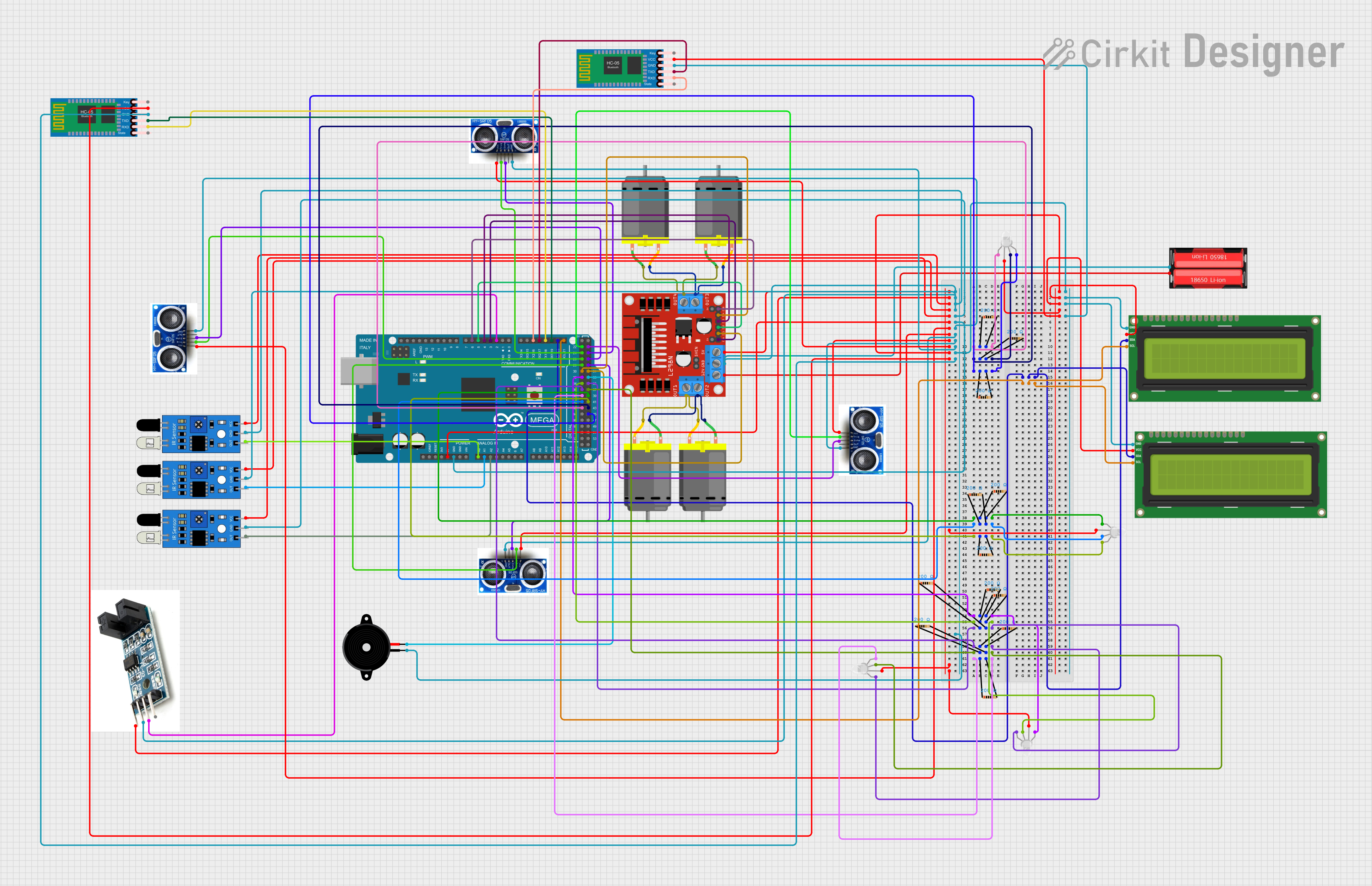
Summary
This circuit is composed of various components including I2C LCD screens, RGB LEDs, DC motors, sensors, a motor driver, a battery, a piezo speaker, an encoder, resistors, Bluetooth modules, and an Arduino Mega 2560 microcontroller. The circuit appears to be designed for a complex system that may involve display interfaces, wireless communication, distance measurement, motor control, and user interaction through an encoder and IR sensors. The Arduino Mega 2560 serves as the central processing unit, interfacing with the various components to control the system's behavior.
Component List
Displays
- I2C LCD 16x2 Screen: A display screen that uses the I2C communication protocol for displaying text.
Indicators
- RGB LED (Wokwi compatible): A light-emitting diode capable of displaying multiple colors by mixing red, green, and blue.
Actuators
- DC Motor: An electric motor that runs on direct current electricity.
- Piezo Speaker: An electronic device that emits sound when an electric signal is applied.
Sensors
- HY-SRF05: An ultrasonic distance sensor that measures the range to an object by using ultrasonic waves.
- ir sensor: An infrared sensor used for detecting obstacles or receiving IR signals.
Power
- 18650 Li-Ion: A rechargeable lithium-ion battery cell.
Control
- L298N DC motor driver: A module that allows control of DC motors with direction and speed control.
- Encoder V1: A rotary encoder that provides feedback on position or rotation.
Communication
- HC-05 Bluetooth Module: A wireless communication module that enables Bluetooth connectivity.
Microcontroller
- Arduino Mega 2560: A microcontroller board based on the ATmega2560 with numerous digital and analog I/O pins.
Passive Components
- Resistor: A passive two-terminal electrical component that implements electrical resistance as a circuit element.
Wiring Details
I2C LCD 16x2 Screen
- Connected to the Arduino Mega 2560 via I2C communication lines (SDA, SCL).
- Powered by 5V and ground connections.
RGB LED (Wokwi compatible)
- Each LED is connected to a digital pin on the Arduino Mega 2560 through a resistor.
- Common anode connected to 5V.
DC Motor
- Connected to the L298N motor driver for control.
- Powered by the 18650 Li-Ion battery through the motor driver.
Piezo Speaker
- One pin connected to a digital pin on the Arduino Mega 2560.
- Other pin connected to ground.
HY-SRF05
- Trigger and echo pins connected to digital pins on the Arduino Mega 2560.
- Powered by 5V and ground connections.
ir sensor
- Output connected to analog pins on the Arduino Mega 2560.
- Powered by 5V and ground connections.
L298N DC motor driver
- Control inputs connected to digital pins on the Arduino Mega 2560.
- Motor outputs connected to DC motors.
- Powered by the 18650 Li-Ion battery.
Encoder V1
- Output connected to a digital pin on the Arduino Mega 2560.
- Powered by 5V and ground connections.
HC-05 Bluetooth Module
- TXD and RXD connected to serial pins on the Arduino Mega 2560 for communication.
- Powered by 5V and ground connections.
Resistor
- Each resistor is connected in series with an RGB LED and a digital pin on the Arduino Mega 2560.
Documented Code
Arduino Mega 2560 Code (sketch.ino)
void setup() {
  // put your setup code here, to run once:

}

void loop() {
  // put your main code here, to run repeatedly:

}
Note: The provided code is a template and does not contain any specific logic to control the circuit. The user must implement the setup and loop functions to initialize and control the components connected to the Arduino Mega 2560.