
ESP32-Based Wireless Communication System with OLED Display and Tactile Switches
View and Edit Project In Cirkit Designer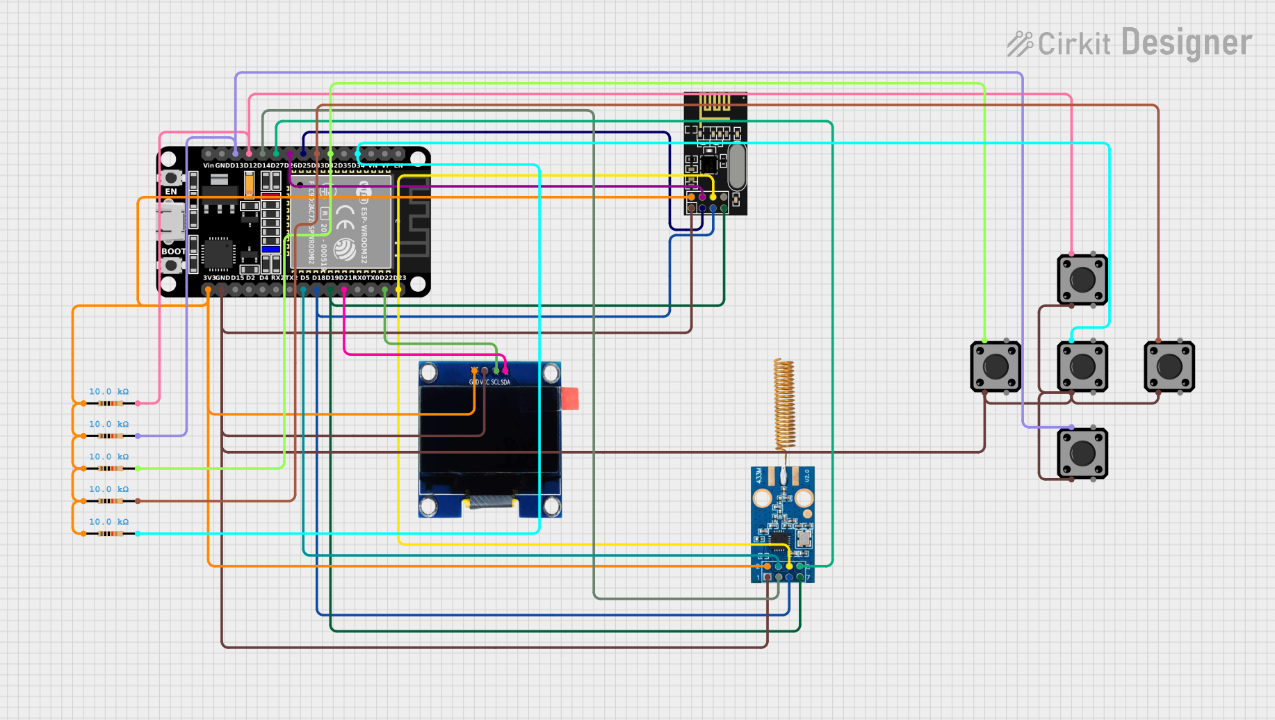
Circuit Documentation
Summary
This document provides a detailed overview of a circuit design that includes an ESP32 microcontroller, an NRF24L01 wireless module, an OLED display, a CC1101 RF module, several tactile switch buttons, and resistors. The circuit is designed to interface these components for various functionalities, including wireless communication and user input.
Component List
ESP32 (30 pin)
- Description: A powerful microcontroller with built-in Wi-Fi and Bluetooth capabilities.
- Pins: EN, VP, VN, D34, D35, D32, D33, D25, D26, D27, D14, D12, D13, GND, Vin, D23, D22, TX0, RX0, D21, D19, D18, D5, TX2, RX2, D4, D2, D15, 3V3
NRF24L01
- Description: A wireless transceiver module for communication over 2.4 GHz.
- Pins: IRQ (not used), MOSI, CSN, VCC (3V), GND, CE, SCK, MISO
OLED 1.3"
- Description: A small OLED display for visual output.
- Pins: GND, VCC, SCL, SDA
CC1101
- Description: A low-power RF transceiver for communication in the 315/433/868/915 MHz ISM/SRD bands.
- Pins: VCC, GND, GDO0, SCLK, SO, GDO2, SI, CSN
Tactile Switch Buttons - 12mm Square
- Description: Momentary push buttons for user input.
- Pins: 3, 1, 4, 2
Resistor
- Description: A 10k Ohm resistor used for pull-up or pull-down configurations.
- Pins: pin1, pin2
- Properties: Resistance: 10k Ohms
Wiring Details
ESP32 (30 pin)
- D34: Connected to pin 2 of a 10k Ohm resistor and pin 1 of a tactile switch button.
- D32: Connected to pin 2 of a 10k Ohm resistor and pin 1 of a tactile switch button.
- D33: Connected to pin 2 of a 10k Ohm resistor and pin 1 of a tactile switch button.
- D25: Connected to CE pin of the NRF24L01.
- D26: Connected to CSN pin of the NRF24L01.
- D27: Connected to GDO2 pin of the CC1101.
- D14: Connected to GDO0 pin of the CC1101.
- D12: Connected to pin 2 of a 10k Ohm resistor and pin 1 of a tactile switch button.
- D13: Connected to pin 2 of a 10k Ohm resistor and pin 1 of a tactile switch button.
- D23: Connected to MOSI pin of the NRF24L01 and SI pin of the CC1101.
- D22: Connected to SCL pin of the OLED display.
- D21: Connected to SDA pin of the OLED display.
- D19: Connected to MISO pin of the NRF24L01 and SO pin of the CC1101.
- D18: Connected to SCK pin of the NRF24L01 and SCLK pin of the CC1101.
- D5: Connected to CSN pin of the CC1101.
- GND: Connected to pin 3 of all tactile switch buttons, GND pin of the NRF24L01, GND pin of the CC1101, and GND pin of the OLED display.
- 3V3: Connected to pin 1 of all 10k Ohm resistors, VCC pin of the NRF24L01, VCC pin of the CC1101, and VCC pin of the OLED display.
NRF24L01
- CE: Connected to D25 pin of the ESP32.
- CSN: Connected to D26 pin of the ESP32.
- MOSI: Connected to D23 pin of the ESP32.
- MISO: Connected to D19 pin of the ESP32.
- SCK: Connected to D18 pin of the ESP32.
- GND: Connected to GND pin of the ESP32.
- VCC (3V): Connected to 3V3 pin of the ESP32.
OLED 1.3"
- GND: Connected to GND pin of the ESP32.
- VCC: Connected to 3V3 pin of the ESP32.
- SCL: Connected to D22 pin of the ESP32.
- SDA: Connected to D21 pin of the ESP32.
CC1101
- VCC: Connected to 3V3 pin of the ESP32.
- GND: Connected to GND pin of the ESP32.
- GDO0: Connected to D14 pin of the ESP32.
- SCLK: Connected to D18 pin of the ESP32.
- SO: Connected to D19 pin of the ESP32.
- GDO2: Connected to D27 pin of the ESP32.
- SI: Connected to D23 pin of the ESP32.
- CSN: Connected to D5 pin of the ESP32.
Tactile Switch Buttons - 12mm Square
- Button 1:
- Pin 1: Connected to pin 2 of a 10k Ohm resistor and D34 pin of the ESP32.
- Pin 3: Connected to GND pin of the ESP32.
- Button 2:
- Pin 1: Connected to pin 2 of a 10k Ohm resistor and D32 pin of the ESP32.
- Pin 3: Connected to GND pin of the ESP32.
- Button 3:
- Pin 1: Connected to pin 2 of a 10k Ohm resistor and D33 pin of the ESP32.
- Pin 3: Connected to GND pin of the ESP32.
- Button 4:
- Pin 1: Connected to pin 2 of a 10k Ohm resistor and D12 pin of the ESP32.
- Pin 3: Connected to GND pin of the ESP32.
- Button 5:
- Pin 1: Connected to pin 2 of a 10k Ohm resistor and D13 pin of the ESP32.
- Pin 3: Connected to GND pin of the ESP32.
Resistor
- Resistor 1:
- Pin 1: Connected to 3V3 pin of the ESP32.
- Pin 2: Connected to pin 1 of a tactile switch button and D34 pin of the ESP32.
- Resistor 2:
- Pin 1: Connected to 3V3 pin of the ESP32.
- Pin 2: Connected to pin 1 of a tactile switch button and D32 pin of the ESP32.
- Resistor 3:
- Pin 1: Connected to 3V3 pin of the ESP32.
- Pin 2: Connected to pin 1 of a tactile switch button and D33 pin of the ESP32.
- Resistor 4:
- Pin 1: Connected to 3V3 pin of the ESP32.
- Pin 2: Connected to pin 1 of a tactile switch button and D12 pin of the ESP32.
- Resistor 5:
- Pin 1: Connected to 3V3 pin of the ESP32.
- Pin 2: Connected to pin 1 of a tactile switch button and D13 pin of the ESP32.
Documented Code
ESP32 Code (sketch.ino)
void setup() {
  // put your setup code here, to run once:

}

void loop() {
  // put your main code here, to run repeatedly:

}
Documentation (documentation.txt)
This document provides a comprehensive overview of the circuit design, including a summary, component list, wiring details, and documented code.