Cirkit Designer
Your all-in-one circuit design IDE
Home /
Project Documentation
ESP32-Based Wi-Fi Connected Weighing System with HX711 Load Cells
Circuit Documentation
Summary
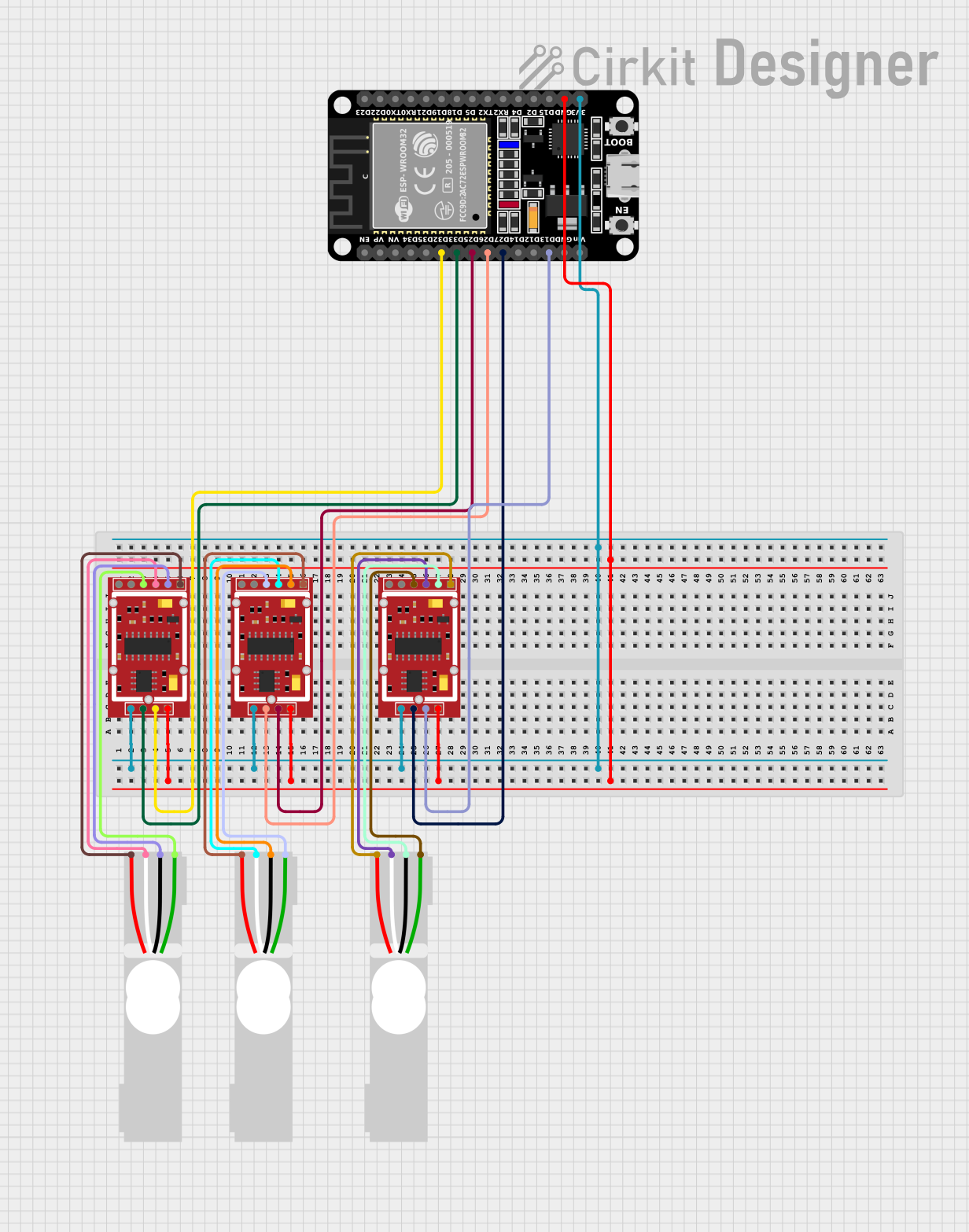
This circuit is designed to read data from three HX711 weighing sensor modules connected to load cells and an ESP32 microcontroller. The ESP32 reads the data from each HX711 module, converts it to grams, and prints it to the serial monitor. Additionally, the ESP32 connects to a WiFi network to potentially send data to a remote server.
Component List
HX711 Weighing Sensor Module
- Description: A precision 24-bit analog-to-digital converter (ADC) designed for weigh scales and industrial control applications.
- Pins: B-, B+, A-, A+, E-, E+, VCC, CK/TX, DO/RX, GND
ESP32 (30 pin)
- Description: A low-cost, low-power system on a chip (SoC) with Wi-Fi and Bluetooth capabilities.
- Pins: EN, VP, VN, D34, D35, D32, D33, D25, D26, D27, D14, D12, D13, GND, Vin, D23, D22, TX0, RX0, D21, D19, D18, D5, TX2, RX2, D4, D2, D15, 3V3
Load Cell - Red/white/black/green
- Description: A transducer that converts force into an electrical signal.
- Pins: E+, A-, E-, A+
Wiring Details
HX711 Weighing Sensor Module 1
- VCC: Connected to 3V3 of ESP32
- GND: Connected to GND of ESP32
- CK/TX: Connected to D33 of ESP32
- DO/RX: Connected to D32 of ESP32
- A-: Connected to A+ of Load Cell 1
- A+: Connected to A- of Load Cell 1
- E-: Connected to E- of Load Cell 1
- E+: Connected to E+ of Load Cell 1
Load Cell 1
- A+: Connected to A- of HX711 Weighing Sensor Module 1
- A-: Connected to A+ of HX711 Weighing Sensor Module 1
- E-: Connected to E- of HX711 Weighing Sensor Module 1
- E+: Connected to E+ of HX711 Weighing Sensor Module 1
HX711 Weighing Sensor Module 2
- VCC: Connected to 3V3 of ESP32
- GND: Connected to GND of ESP32
- CK/TX: Connected to D26 of ESP32
- DO/RX: Connected to D25 of ESP32
- A-: Connected to A+ of Load Cell 2
- A+: Connected to A- of Load Cell 2
- E-: Connected to E- of Load Cell 2
- E+: Connected to E+ of Load Cell 2
Load Cell 2
- A+: Connected to A- of HX711 Weighing Sensor Module 2
- A-: Connected to A+ of HX711 Weighing Sensor Module 2
- E-: Connected to E- of HX711 Weighing Sensor Module 2
- E+: Connected to E+ of HX711 Weighing Sensor Module 2
HX711 Weighing Sensor Module 3
- VCC: Connected to 3V3 of ESP32
- GND: Connected to GND of ESP32
- CK/TX: Connected to D27 of ESP32
- DO/RX: Connected to D13 of ESP32
- A-: Connected to A+ of Load Cell 3
- A+: Connected to A- of Load Cell 3
- E-: Connected to E- of Load Cell 3
- E+: Connected to E+ of Load Cell 3
Load Cell 3
- A+: Connected to A- of HX711 Weighing Sensor Module 3
- A-: Connected to A+ of HX711 Weighing Sensor Module 3
- E-: Connected to E- of HX711 Weighing Sensor Module 3
- E+: Connected to E+ of HX711 Weighing Sensor Module 3
Code Documentation
/*
 * This Arduino Sketch is for an ESP32 microcontroller that reads data from
 * three HX711 weighing sensor modules connected to load cells. The data
 * from each HX711 module is read, converted to grams, and printed to the
 * serial monitor. In addition, the ESP32 connects to a provided internet
 * network. The program should always start to tare, getting the 3 scales
 * to a zero value before providing the readings.
 */

#include "HX711.h"
#include <WiFi.h>
#include <FirebaseESP32.h>

// Pin definitions for HX711 modules
#define LOADCELL_DOUT1 32
#define LOADCELL_SCK1 33
#define LOADCELL_DOUT2 25
#define LOADCELL_SCK2 26
#define LOADCELL_DOUT3 13
#define LOADCELL_SCK3 27

// WiFi credentials
#define WIFI_SSID "SmartMeds"
#define WIFI_PASSWORD "SmartMeds"

// Calibration factors for each scale
#define CALIBRATION_FACTOR1 2280.0
#define CALIBRATION_FACTOR2 2280.0
#define CALIBRATION_FACTOR3 2280.0

// Create HX711 objects
HX711 scale1;
HX711 scale2;
HX711 scale3;

void setup() {
  Serial.begin(115200);
  // Initialize HX711 modules
  scale1.begin(LOADCELL_DOUT1, LOADCELL_SCK1);
  scale2.begin(LOADCELL_DOUT2, LOADCELL_SCK2);
  scale3.begin(LOADCELL_DOUT3, LOADCELL_SCK3);

  // Set calibration factors
  scale1.set_scale(CALIBRATION_FACTOR1);
  scale2.set_scale(CALIBRATION_FACTOR2);
  scale3.set_scale(CALIBRATION_FACTOR3);

  // Tare scales to zero
  scale1.tare();
  scale2.tare();
  scale3.tare();

  // Connect to WiFi
  WiFi.begin(WIFI_SSID, WIFI_PASSWORD);
  while (WiFi.status() != WL_CONNECTED) {
    delay(1000);
    Serial.println("Connecting to WiFi...");
  }
  Serial.println("Connected to WiFi");
}

void loop() {
  // Read and print data from each HX711 module
  if (scale1.is_ready()) {
    float weight1 = scale1.get_units();
    Serial.print("Scale 1: ");
    Serial.print(weight1);
    Serial.println(" g");
  } else {
    Serial.println("Scale 1 not found.");
  }

  if (scale2.is_ready()) {
    float weight2 = scale2.get_units();
    Serial.print("Scale 2: ");
    Serial.print(weight2);
    Serial.println(" g");
  } else {
    Serial.println("Scale 2 not found.");
  }

  if (scale3.is_ready()) {
    float weight3 = scale3.get_units();
    Serial.print("Scale 3: ");
    Serial.print(weight3);
    Serial.println(" g");
  } else {
    Serial.println("Scale 3 not found.");
  }

  delay(2500); // Wait for 2 seconds before next read
}
This code initializes the HX711 modules, sets their calibration factors, tares the scales, and connects the ESP32 to a WiFi network. In the main loop, it reads the weight data from each HX711 module and prints it to the serial monitor.