
Arduino-Controlled Environmental Monitoring System with OLED Display and Sonar Level Sensing
View and Edit Project In Cirkit Designer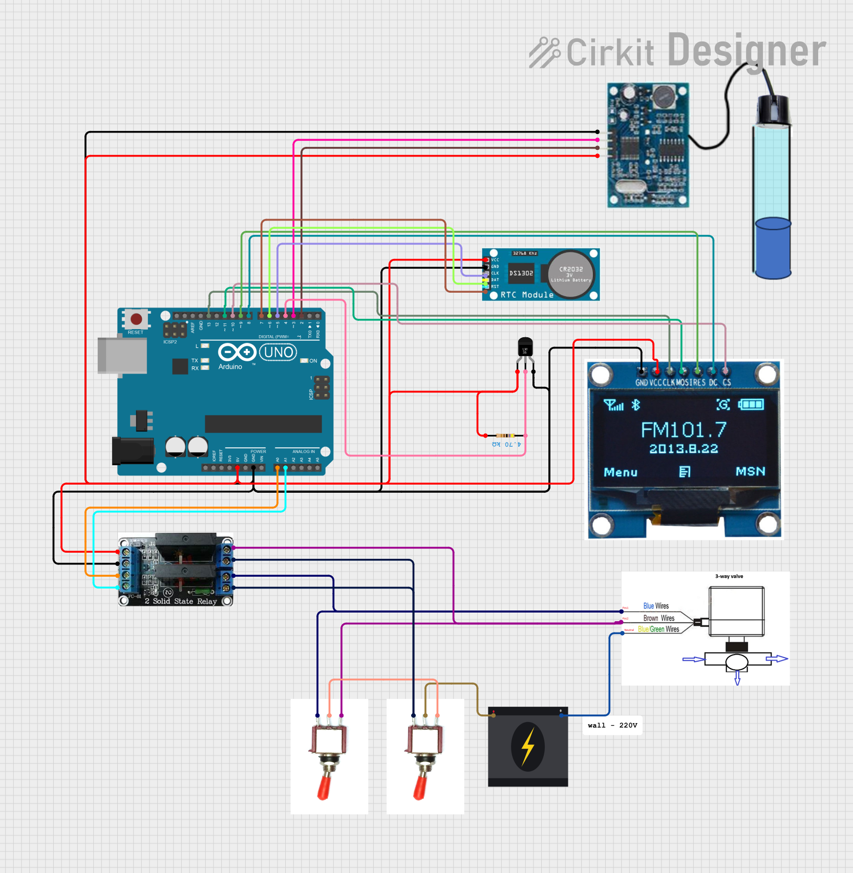
Circuit Documentation
Summary
The circuit described in the provided design includes a variety of components that interact to perform specific functions. The circuit is powered by a 240V power source and includes an Arduino UNO microcontroller as the central processing unit. The circuit features a 3-way ball valve controlled by solid-state relays, which are in turn managed by the Arduino. Input and output devices include a temperature sensor (LM35), a real-time clock (RTC), an OLED display module, and a sonar sensor within a watertube. Toggle switches are used to control the flow of power within the circuit. A resistor is also included, likely for current limiting or voltage division purposes.
Component List
- 3-way Ball Valve: A valve used to control the flow of a fluid, with three different positions.
- 240V Power Source: The main power supply for the circuit, providing a 240V alternating current.
- Toggle Switches: Two switches used to control the connection of the circuit to the power source or other components.
- Arduino UNO: A microcontroller board based on the ATmega328P, used for controlling the various components of the circuit.
- OLED Display Module: A 1.3-inch display used for visual output from the circuit.
- RTC (Real-Time Clock): A clock module used to keep track of the current time and date.
- Temperature Sensor (LM35): A precision integrated-circuit temperature device used for measuring temperature.
- Resistor: A passive two-terminal electrical component that implements electrical resistance as a circuit element.
- Solid State Relay: An electronic switching device that allows for controlling high power devices with low power signals from the microcontroller.
- Sonar in Watertube: A sensor used to measure the distance to an object by using sound waves.
Wiring Details
3-way Ball Valve
- Pos1 (Blue): Connected to the ground (Gnd) of a Toggle Switch and channel 2A of the Solid State Relay.
- Pos2 (Brown): Connected to the Vcc of a Toggle Switch and channel 1A of the Solid State Relay.
- Neutral (Yellow-Green): Connected to the Neutral pin of the 240V Power Source.
240V Power Source
- Live: Connected to the Sig pin of a Toggle Switch.
- Neutral: Connected to the Neutral (Yellow-Green) pin of the 3-way Ball Valve.
Toggle Switches
- Vcc: One switch's Vcc is connected to the Pos2 (Brown) of the 3-way Ball Valve and the other switch's Vcc is connected to the Sig of the other Toggle Switch.
- Sig: One switch's Sig is connected to the Live of the 240V Power Source, and the other switch's Sig is connected to the Vcc of the other Toggle Switch.
- Gnd: One switch's Gnd is connected to the Pos1 (Blue) of the 3-way Ball Valve and channels 1B and 2B of the Solid State Relay. The other switch's Gnd is connected to the same channels of the Solid State Relay.
Arduino UNO
- 5V: Powers the Temperature Sensor, RTC, OLED Display, Resistor, Sonar Sensor, and Solid State Relay.
- GND: Common ground for the Temperature Sensor, RTC, OLED Display, Sonar Sensor, and Solid State Relay.
- A0: Connected to channel CH1 of the Solid State Relay.
- A1: Connected to channel CH2 of the Solid State Relay.
- D2-D13: Various connections to the OLED Display, RTC, Temperature Sensor, and Sonar Sensor for control and data transfer.
OLED Display Module
- CS: Connected to D10 on the Arduino UNO.
- GND: Common ground with Arduino UNO.
- VCC: Powered by 5V from Arduino UNO.
- CLK: Connected to D13 on the Arduino UNO.
- MOSI: Connected to D11 on the Arduino UNO.
- RES: Connected to D9 on the Arduino UNO.
- DC: Connected to D8 on the Arduino UNO.
RTC
- VCC: Powered by 5V from Arduino UNO.
- GND: Common ground with Arduino UNO.
- CLK: Connected to D5 on the Arduino UNO.
- DAT: Connected to D6 on the Arduino UNO.
- RST: Connected to D7 on the Arduino UNO.
Temperature Sensor (LM35)
- +Vs: Powered by 5V from Arduino UNO.
- Vout: Connected to D4 on the Arduino UNO and one pin of the Resistor.
- GND: Common ground with Arduino UNO.
Resistor
- Pin1: Connected to Vout of the Temperature Sensor and D4 on the Arduino UNO.
- Pin2: Powered by 5V from Arduino UNO.
Solid State Relay
- CH1: Connected to A0 on the Arduino UNO.
- CH2: Connected to A1 on the Arduino UNO.
- 5V: Powered by 5V from Arduino UNO.
- GND: Common ground with Arduino UNO.
- 1A: Connected to Pos2 (Brown) of the 3-way Ball Valve.
- 1B: Connected to Gnd of a Toggle Switch.
- 2A: Connected to Pos1 (Blue) of the 3-way Ball Valve.
- 2B: Connected to Gnd of a Toggle Switch.
Sonar in Watertube
- GND: Common ground with Arduino UNO.
- TX/TRIG: Connected to D3 on the Arduino UNO.
- RX/ECHO: Connected to D2 on the Arduino UNO.
- 5V: Powered by 5V from Arduino UNO.
Documented Code
Arduino UNO Code (sketch.ino)
void setup() {
  // put your setup code here, to run once:

}

void loop() {
  // put your main code here, to run repeatedly:

}
Note: The provided code for the Arduino UNO is a template with empty setup and loop functions. Actual functionality needs to be implemented based on the requirements of the circuit.
Additional Documentation (documentation.txt)
No additional documentation code was provided.