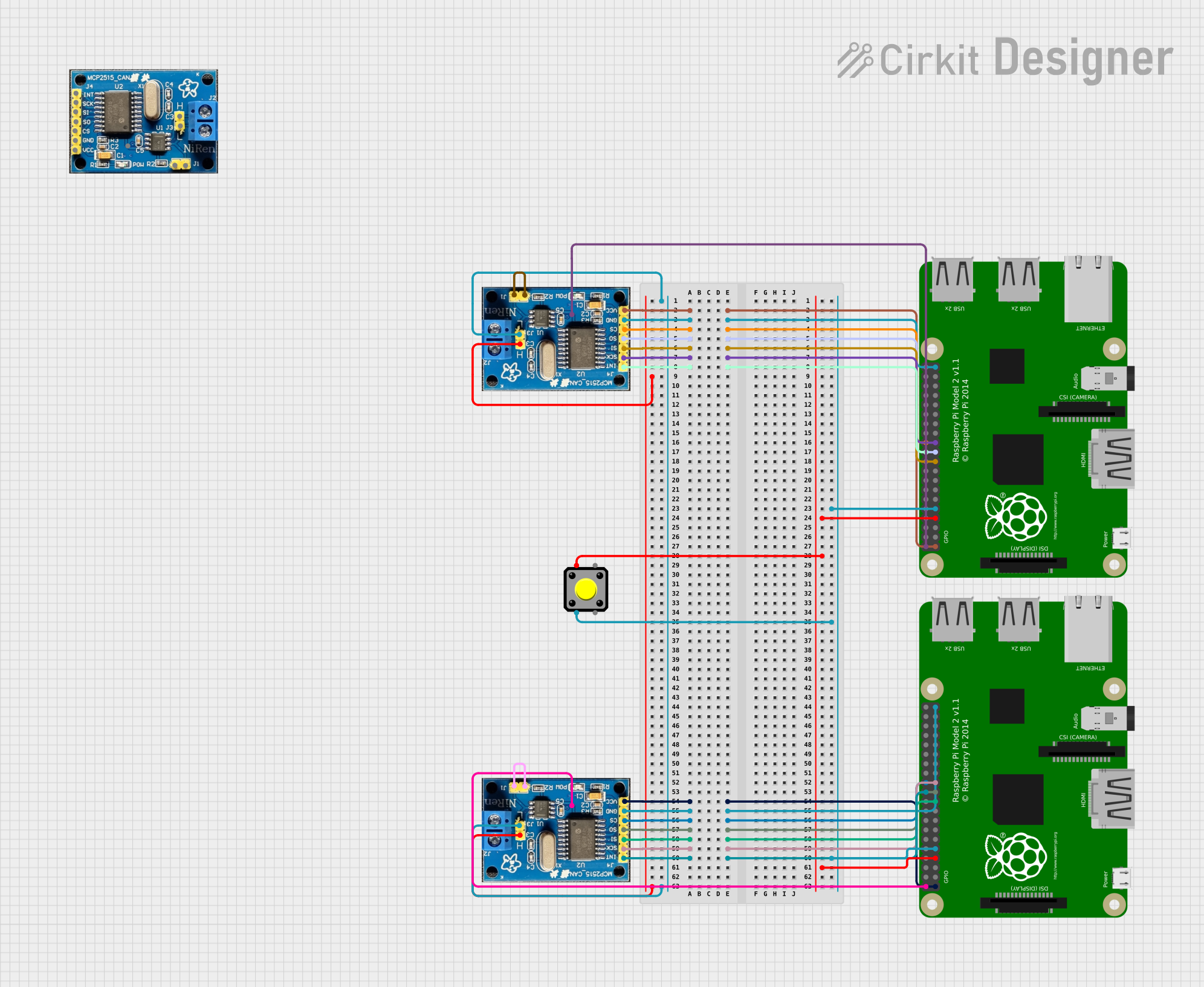
Dual Raspberry Pi 2B CAN BUS Communication Interface with Pushbutton Interaction

Circuit Documentation
Summary
This circuit integrates two Raspberry Pi 2B microcontrollers with multiple CAN BUS modules and a pushbutton. The Raspberry Pi microcontrollers serve as the central processing units, interfacing with the CAN BUS modules for communication purposes. The pushbutton is used as an input device, potentially for triggering events or actions on the Raspberry Pis. The CAN BUS modules are connected to each other via their high (H) and low (L) pins to form a differential signal pair for robust communication. Power and ground connections are distributed appropriately among the components, and several GPIO pins on the Raspberry Pis are used to interface with the CAN BUS modules.
Component List
Raspberry Pi 2B
- Description: A microcontroller board based on the Broadcom BCM2836 SoC, which includes an ARM Cortex-A7 CPU and various I/O options.
- Pins: 3v3, GPIO2, GPIO3, GPIO4, GND, GPIO17, GPIO27, GPIO22, 3V3, GPIO10, GPIO9, GPIO11, ID_SD, GPIO5, GPIO6, GPIO13, GPIO19, GPIO26, GPIO21, GPIO20, GPIO16, GPIO12, ID_SC, GPIO7, GPIO8, GPIO25, GPIO24, GPIO23, GPIO18, GPIO15, GPIO14, 5V
CAN BUS
- Description: A module used for automotive communication networks, allowing microcontrollers and devices to communicate with each other without a host computer.
- Pins: INT, SCK, SI, SO, CS, GND, VCC, J1, J11, H, L, VDD
Pushbutton
- Description: A simple switch mechanism for controlling some aspect of a machine or a process. Buttons are typically made out of hard material, usually plastic or metal.
- Pins: Pin 2, Pin 1, Pin 3, Pin 4
Wiring Details
Raspberry Pi 2B to CAN BUS Wiring
- 3v3 (Raspberry Pi) to VCC (CAN BUS)
- GND (Raspberry Pi) to GND (CAN BUS)
- GPIO8 (Raspberry Pi) to CS (CAN BUS)
- GPIO9 (Raspberry Pi) to SO (CAN BUS)
- GPIO10 (Raspberry Pi) to SI (CAN BUS)
- GPIO11 (Raspberry Pi) to SCK (CAN BUS)
- GPIO25 (Raspberry Pi) to INT (CAN BUS)
- 5V (Raspberry Pi) to VDD (CAN BUS)
CAN BUS to CAN BUS Wiring
- H (CAN BUS) to H (CAN BUS)
- L (CAN BUS) to L (CAN BUS)
- J1 (CAN BUS) to J11 (CAN BUS)
Raspberry Pi 2B to Pushbutton Wiring
- GPIO4 (Raspberry Pi) to Pin 1 (Pushbutton)
- GND (Raspberry Pi) to Pin 2 (Pushbutton)
Documented Code
Raspberry Pi 2B - sketch.ino
void setup() {
  // put your setup code here, to run once:

}

void loop() {
  // put your main code here, to run repeatedly:

}
Raspberry Pi 2B - documentation.txt
(No content in the provided documentation file)
Please note that the provided code is a template with no specific functionality. The actual implementation will depend on the desired behavior of the Raspberry Pi 2B in the circuit.