Cirkit Designer
Your all-in-one circuit design IDE
Home /
Project Documentation
Arduino RFID Door Lock System with LCD Display and Servo Motor
Circuit Documentation
Summary
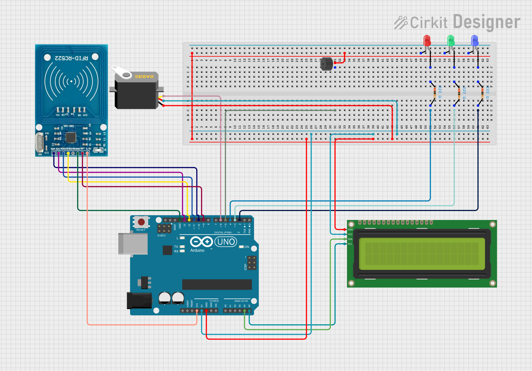
This circuit is an RFID-based door lock system using an Arduino UNO. The system includes an RFID reader, an LCD display, a servo motor for locking and unlocking, LEDs for status indication, and a buzzer for alerting invalid access. The Arduino UNO controls all components and processes the RFID tags to determine access.
Component List
Arduino UNO
- Description: Microcontroller board based on the ATmega328P.
- Pins: UNUSED, IOREF, Reset, 3.3V, 5V, GND, Vin, A0, A1, A2, A3, A4, A5, SCL, SDA, AREF, D13, D12, D11, D10, D9, D8, D7, D6, D5, D4, D3, D2, D1, D0
LED: Two Pin (red)
- Description: Red LED.
- Pins: cathode, anode
LED: Two Pin (blue)
- Description: Blue LED.
- Pins: cathode, anode
LED: Two Pin (green)
- Description: Green LED.
- Pins: cathode, anode
Resistor (220 Ohms)
- Description: Resistor with 220 Ohms resistance.
- Pins: pin1, pin2
Servo
- Description: Servo motor for locking and unlocking.
- Pins: gnd, vcc, pulse
16x2 I2C LCD
- Description: 16x2 character LCD with I2C interface.
- Pins: GND, VCC, SDA, SCL
RFID-RC522
- Description: RFID reader module.
- Pins: VCC (3.3V), RST, GND, IRQ, MISO, MOSI, SCK, SDA
Buzzer
- Description: Buzzer for alerting invalid access.
- Pins: PIN, GND
Wiring Details
Arduino UNO
- D2: Connected to pin2 of a 220 Ohm resistor (green LED).
- D3: Connected to pin2 of a 220 Ohm resistor (blue LED).
- D4: Connected to pin2 of a 220 Ohm resistor (red LED).
- D5: Connected to PIN of the buzzer.
- D6: Connected to pulse pin of the servo.
- D9: Connected to RST pin of the RFID-RC522.
- D10: Connected to SDA pin of the RFID-RC522.
- D11: Connected to MOSI pin of the RFID-RC522.
- D12: Connected to MISO pin of the RFID-RC522.
- D13: Connected to SCK pin of the RFID-RC522.
- A4: Connected to SDA pin of the 16x2 I2C LCD.
- A5: Connected to SCL pin of the 16x2 I2C LCD.
- 3.3V: Connected to VCC (3.3V) pin of the RFID-RC522.
- 5V: Connected to VCC pin of the 16x2 I2C LCD and vcc pin of the servo.
- GND: Connected to cathode pins of all LEDs, GND pin of the buzzer, GND pin of the 16x2 I2C LCD, gnd pin of the servo, and GND pin of the RFID-RC522.
LED: Two Pin (red)
- cathode: Connected to GND.
- anode: Connected to pin1 of a 220 Ohm resistor.
LED: Two Pin (blue)
- cathode: Connected to GND.
- anode: Connected to pin1 of a 220 Ohm resistor.
LED: Two Pin (green)
- cathode: Connected to GND.
- anode: Connected to pin1 of a 220 Ohm resistor.
Resistor (220 Ohms)
- pin1: Connected to anode of respective LED.
- pin2: Connected to respective Arduino UNO digital pin (D2, D3, D4).
Servo
- gnd: Connected to GND.
- vcc: Connected to 5V.
- pulse: Connected to D6.
16x2 I2C LCD
- GND: Connected to GND.
- VCC: Connected to 5V.
- SDA: Connected to A4.
- SCL: Connected to A5.
RFID-RC522
- VCC (3.3V): Connected to 3.3V.
- RST: Connected to D9.
- GND: Connected to GND.
- SCK: Connected to D13.
- MISO: Connected to D12.
- MOSI: Connected to D11.
- SDA: Connected to D10.
Buzzer
- PIN: Connected to D5.
- GND: Connected to GND.
Code Documentation
Sketch.ino
#include <SPI.h>
#include <MFRC522.h>

#define RST_PIN 9
#define SS_PIN  10

MFRC522 mfrc522(SS_PIN, RST_PIN);
String UIDCard = "";

void setup() {
  Serial.begin(9600);
  SPI.begin();
  mfrc522.PCD_Init();
  Serial.println("Scan your RFID Card:");
  for (int i = 0; i < 20; i++) {
    Serial.print(".");
    delay(50);
  }
  Serial.println("");
}

void loop() {
  while (getUID()) {
    Serial.print("UID: ");
    Serial.println(UIDCard);

    for (int i = 0; i < 20; i++) {
      Serial.print(".");
      delay(50);
    }
    delay(3000);
  }
}

boolean getUID() {
  if (!mfrc522.PICC_IsNewCardPresent()) {
    return false;
  }

  if (!mfrc522.PICC_ReadCardSerial()) {
    return false;
  }
  UIDCard = "";
  for (byte i = 0; i < mfrc522.uid.size; i++) {
    UIDCard.concat(String(mfrc522.uid.uidByte[i] < 0x10 ? " 0" : " "));
    UIDCard.concat(String(mfrc522.uid.uidByte[i], HEX));
  }
  UIDCard.toUpperCase();
  UIDCard = UIDCard.substring(1);

  mfrc522.PICC_HaltA();
  return true;
}
master.cpp
#include <SPI.h>
#include <MFRC522.h>

#define RST_PIN 9
#define SS_PIN  10

MFRC522 mfrc522(SS_PIN, RST_PIN);
String UIDCard = "";

void setup() {
  Serial.begin(9600);
  SPI.begin();
  mfrc522.PCD_Init();
  Serial.println("Scan your RFID Card:");
  for (int i = 0; i < 20; i++) {
    Serial.print(".");
    delay(50);
  }
  Serial.println("");
}

void loop() {
  while (getUID()) {
    Serial.print("UID: ");
    Serial.println(UIDCard);

    for (int i = 0; i < 20; i++) {
      Serial.print(".");
      delay(50);
    }
    delay(3000);
  }
}

boolean getUID() {
  if (!mfrc522.PICC_IsNewCardPresent()) {
    return false;
  }

  if (!mfrc522.PICC_ReadCardSerial()) {
    return false;
  }
  UIDCard = "";
  for (byte i = 0; i < mfrc522.uid.size; i++) {
    UIDCard.concat(String(mfrc522.uid.uidByte[i] < 0x10 ? " 0" : " "));
    UIDCard.concat(String(mfrc522.uid.uidByte[i], HEX));
  }
  UIDCard.toUpperCase();
  UIDCard = UIDCard.substring(1);

  mfrc522.PICC_HaltA();
  return true;
}
door.cpp
/*
 * Arduino RFID Door Lock
 * Components: RFID-RC522, LCD, Buzzer, Red LED, Blue LED, Green LED,
 * 3x 220 Ohm Resistors, Arduino UNO, Servo Motor
 *
 * This code controls an RFID-based door lock system. When a valid RFID tag
 * is detected, the servo motor unlocks the door, the green LED lights up,
 * and a message is displayed on the LCD. If an invalid tag is detected,
 * the red LED lights up and the buzzer sounds. The blue LED indicates
 * system readiness.
 */

#include <SPI.h>
#include <MFRC522.h>
#include <Wire.h>
#include <LiquidCrystal_I2C.h>
#include <Servo.h>

#define SS_PIN 10
#define RST_PIN 9