
Circuit Documentation
Summary
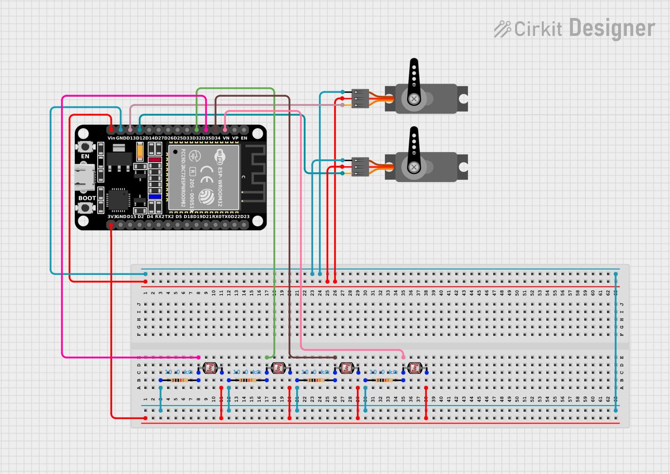
This circuit involves an ESP32 microcontroller interfacing with multiple sensors and actuators. The sensors include several photocells (LDRs) and resistors, while the actuators are two servos. The ESP32 reads data from the photocells and controls the servos based on the input.
Component List
ESP32 (30 pin)
- Description: A powerful microcontroller with built-in Wi-Fi and Bluetooth capabilities.
- Pins: EN, VP, VN, D34, D35, D32, D33, D25, D26, D27, D14, D12, D13, GND, Vin, D23, D22, TX0, RX0, D21, D19, D18, D5, TX2, RX2, D4, D2, D15, 3V3
Servo (x2)
- Description: A small actuator that can be controlled to rotate to a specific angle.
- Pins: GND, VCC, PWM
Resistor (x5)
- Description: A passive electrical component that implements electrical resistance as a circuit element.
- Pins: pin1, pin2
- Properties: Resistance = 10,000 Ohms
Photocell (LDR) (x4)
- Description: A light-dependent resistor that changes its resistance based on the amount of light it is exposed to.
- Pins: pin 0, pin 1
Wiring Details
ESP32 (30 pin)
GND is connected to:
- Resistor pin1
- Servo GND (both servos)
D35 is connected to:
- Resistor pin2
- Photocell (LDR) pin 0
3V3 is connected to:
- Photocell (LDR) pin 1 (all four photocells)
D32 is connected to:
- Resistor pin2
- Photocell (LDR) pin 0
D34 is connected to:
- Resistor pin2
- Photocell (LDR) pin 0
VN is connected to:
- Resistor pin2
- Photocell (LDR) pin 0
Vin is connected to:
- Servo VCC (both servos)
D12 is connected to:
- Servo PWM
D13 is connected to:
- Servo PWM
Servo
GND is connected to:
- ESP32 GND
VCC is connected to:
- ESP32 Vin
PWM is connected to:
- ESP32 D12 (for one servo)
- ESP32 D13 (for the other servo)
Resistor
pin1 is connected to:
- ESP32 GND
pin2 is connected to:
- ESP32 D35 (for one resistor)
- ESP32 D32 (for another resistor)
- ESP32 D34 (for another resistor)
- ESP32 VN (for another resistor)
Photocell (LDR)
pin 0 is connected to:
- Resistor pin2
pin 1 is connected to:
- ESP32 3V3
Code
There is no code provided for this circuit.