
ESP32-Controlled Relay with Bluetooth for Smart Home Automation
View and Edit Project In Cirkit Designer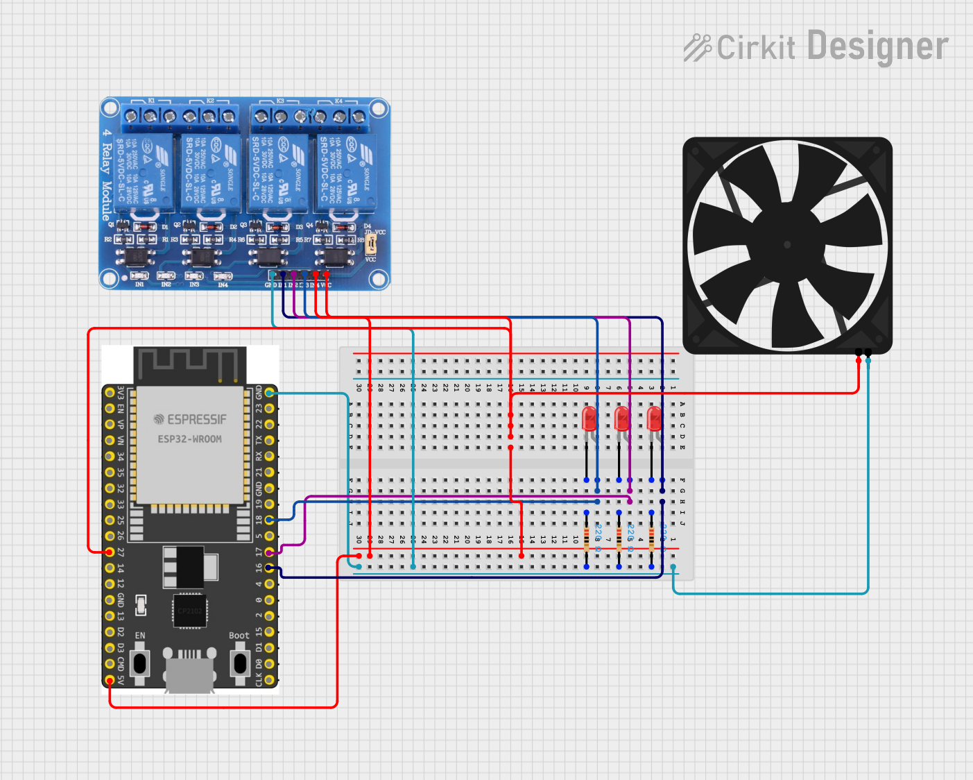
Circuit Documentation
Summary
This circuit is designed to control a series of LEDs and a fan using an ESP32 Wroom Dev Kit microcontroller. The ESP32 is programmed to communicate via Bluetooth, allowing for wireless control of the connected devices. The circuit includes a 4-channel relay module to switch higher loads that the ESP32 cannot directly drive. The LEDs are connected through resistors to limit the current, and the fan is powered by a 5V supply. The ESP32 controls the relay module, which in turn controls the power to the LEDs and the fan.
Component List
Relay 4 Channel 5v
- Description: A 4-channel relay module capable of controlling up to four separate circuits.
- Pins: GND, IN1, IN2, IN3, IN4, VCC, COM1, COM2, COM3, COM4, NO1, NO2, NO3, NO4, NC1, NC2, NC3, NC4
LED: Two Pin (red)
- Description: A standard red LED with two pins, anode, and cathode.
- Pins: cathode, anode
Fan
- Description: A 5V fan used for cooling or ventilation purposes.
- Pins: GND, 5V
ESP 32 Wroom Dev Kit
- Description: A microcontroller development board based on the ESP32 chip, featuring Wi-Fi and Bluetooth connectivity.
- Pins: 3V3, EN, VP, VN, GPIO 34, GPIO 35, GPIO 32, GPIO 33, GPIO 25, GPIO 26, GPIO 27, GPIO 14, GND, GPIO 13, SD2, SD3, CMD, V5, GPIO 23, GPIO 22, TXD, RXD, GPIO 21, GPIO 19, GPIO 18, GPIO 5, GPIO 17, GPIO 16, GPIO 4, GPIO 0, GPIO 2, GPIO 15, SD1, SD0, CLK
Resistor
- Description: A resistor with a resistance value of 220 Ohms, used to limit current to the LEDs.
- Pins: pin1, pin2
- Properties: Resistance: 220 Ohms
Wiring Details
Relay 4 Channel 5v
- GND: Connected to the ground net, shared with the Fan, ESP32, and all Resistors.
- IN1, IN2, IN3: Controlled by GPIO 16, GPIO 17, and GPIO 18 of the ESP32 respectively.
- IN4: Controls the Fan via the 5V connection.
- VCC: Connected to the 5V output of the ESP32.
LED: Two Pin (red)
- Anode: Connected to the corresponding IN pin on the Relay 4 Channel 5v module.
- Cathode: Connected to pin1 of the corresponding Resistor.
Fan
- GND: Connected to the ground net.
- 5V: Controlled by IN4 on the Relay 4 Channel 5v module.
ESP 32 Wroom Dev Kit
- GND: Connected to the ground net.
- GPIO 16, GPIO 17, GPIO 18: Control the IN1, IN2, and IN3 pins on the Relay 4 Channel 5v module respectively.
- GPIO 27: Controls the IN4 pin on the Relay 4 Channel 5v module, which in turn controls the Fan.
- V5: Provides 5V power to the Relay 4 Channel 5v module.
Resistor
- pin1: Connected to the cathode of the corresponding LED.
- pin2: Connected to the ground net.
Documented Code
#include <BluetoothSerial.h>

BluetoothSerial ESP_BT;

int lamp1 = 16;  // GPIO for Lamp 1
int lamp2 = 17;  // GPIO for Lamp 2
int lamp3 = 18;  // GPIO for Lamp 3
int fan = 27;    // GPIO for Fan

void setup() {
  Serial.begin(9600);
  ESP_BT.begin("ESP32_Control");  // Bluetooth device name

  // Set pins as OUTPUT
  pinMode(lamp1, OUTPUT);
  pinMode(lamp2, OUTPUT);
  pinMode(lamp3, OUTPUT);
  pinMode(fan, OUTPUT);
}

void loop() {
  if (ESP_BT.available()) {
    char command = ESP_BT.read();
    switch (command) {
      case '1': digitalWrite(lamp1, HIGH); break; // Turn on Lamp 1
      case '2': digitalWrite(lamp1, LOW); break;  // Turn off Lamp 1
      case '3': digitalWrite(lamp2, HIGH); break; // Turn on Lamp 2
      case '4': digitalWrite(lamp2, LOW); break;  // Turn off Lamp 2
      case '5': digitalWrite(lamp3, HIGH); break; // Turn on Lamp 3
      case '6': digitalWrite(lamp3, LOW); break;  // Turn off Lamp 3
      case '7': digitalWrite(fan, HIGH); break;   // Turn on Fan
      case '8': digitalWrite(fan, LOW); break;    // Turn off Fan
    }
  }
}
This code snippet is responsible for setting up the ESP32's Bluetooth functionality and configuring the GPIO pins to control the relay module. The loop function listens for incoming Bluetooth commands and toggles the corresponding GPIO pins to control the LEDs and the fan.