
Arduino Nano-Based Adjustable Power Supply with Bluetooth and LED Indicators
View and Edit Project In Cirkit Designer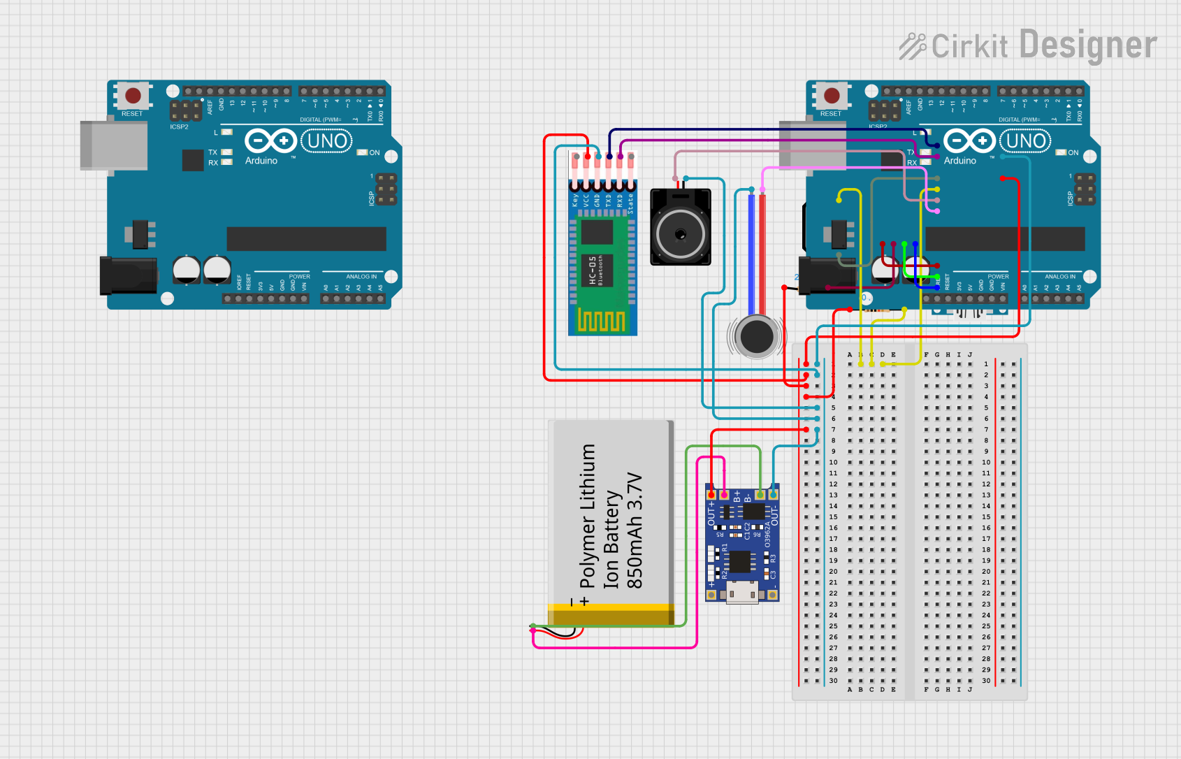
Circuit Documentation
Summary
This circuit is an adjustable power supply system built around an Arduino Nano microcontroller. It includes various components such as LEDs, a loudspeaker, a vibration motor, a pushbutton, a Bluetooth module (HC-05), a battery charging module (TP4056), and a Polymer Lithium Ion Battery. The system allows for setting and displaying desired voltage and current values on a TFT screen, and it also displays the actual voltage, current, and power drawn by the connected load.
Component List
LED: Four Pin (Common Cathode)
- Pins: red anode, common cathode, green anode, blue anode
- Description: RGB LED with a common cathode configuration.
Loudspeaker
- Pins: pin1, pin2
- Description: Standard loudspeaker for audio output.
Vibration Motor
- Pins: POS, NEG
- Description: Small vibration motor for haptic feedback.
Arduino Nano
- Pins: D1/TX, D0/RX, RESET, GND, D2, D3, D4, D5, D6, D7, D8, D9, D10, D11/MOSI, D12/MISO, VIN, 5V, A7, A6, A5, A4, A3, A2, A1, A0, AREF, 3V3, D13/SCK
- Description: Microcontroller board based on the ATmega328P.
Resistor (220 Ohms)
- Pins: pin1, pin2
- Description: Resistor with a resistance of 220 Ohms.
Pushbutton
- Pins: Pin 2, Pin 1, Pin 3, Pin 4
- Description: Standard pushbutton for user input.
HC-05 Bluetooth Module
- Pins: EN, VCC, GND, TXD, RXD, STATE
- Description: Bluetooth module for wireless communication.
TP4056 Battery Charging Module
- Pins: OUT-, B-, B+, OUT+, IN-, IN+
- Description: Lithium-ion battery charging module.
Polymer Lithium Ion Battery - 850mAh
- Pins: GND, VCC
- Description: Rechargeable lithium-ion battery with a capacity of 850mAh.
Resistor (10k Ohms)
- Pins: pin1, pin2
- Description: Resistor with a resistance of 10k Ohms.
Arduino UNO
- Pins: UNUSED, IOREF, Reset, 3.3V, 5V, GND, Vin, A0, A1, A2, A3, A4, A5, SCL, SDA, AREF, D13, D12, D11, D10, D9, D8, D7, D6, D5, D4, D3, D2, D1, D0
- Description: Microcontroller board based on the ATmega328P.
Wiring Details
LED: Four Pin (Common Cathode)
- red anode: Connected to Arduino Nano pin D9
- common cathode: Connected to Resistor (220 Ohms) pin2
- green anode: Connected to Arduino Nano pin D10
- blue anode: Connected to Arduino Nano pin D11/MOSI
Loudspeaker
- pin1: Connected to Arduino Nano GND
- pin2: Connected to Arduino Nano pin D3
Vibration Motor
- POS: Connected to Arduino Nano pin D4
- NEG: Connected to Arduino Nano GND
Arduino Nano
- D1/TX: Connected to HC-05 TXD
- D0/RX: Connected to HC-05 RXD
- GND: Connected to HC-05 GND, Loudspeaker pin1, Vibration Motor NEG, TP4056 OUT-, Pushbutton Pin 1
- D2: Connected to Pushbutton Pin 2, Resistor (10k Ohms) pin2
- D3: Connected to Loudspeaker pin2
- D4: Connected to Vibration Motor POS
- D9: Connected to LED red anode
- D10: Connected to LED green anode
- D11/MOSI: Connected to LED blue anode
- 5V: Connected to HC-05 VCC, Resistor (220 Ohms) pin1, Resistor (10k Ohms) pin1, TP4056 OUT+
Resistor (220 Ohms)
- pin1: Connected to Arduino Nano 5V
- pin2: Connected to LED common cathode
Pushbutton
- Pin 2: Connected to Resistor (10k Ohms) pin2, Arduino Nano pin D2
- Pin 1: Connected to Arduino Nano GND
HC-05 Bluetooth Module
- VCC: Connected to Arduino Nano 5V
- GND: Connected to Arduino Nano GND
- TXD: Connected to Arduino Nano D1/TX
- RXD: Connected to Arduino Nano D0/RX
TP4056 Battery Charging Module
- OUT+: Connected to Arduino Nano 5V, Resistor (220 Ohms) pin1, Resistor (10k Ohms) pin1
- OUT-: Connected to Arduino Nano GND, Loudspeaker pin1, Vibration Motor NEG
- B-: Connected to Polymer Lithium Ion Battery GND
- B+: Connected to Polymer Lithium Ion Battery VCC
Polymer Lithium Ion Battery - 850mAh
- GND: Connected to TP4056 B-
- VCC: Connected to TP4056 B+
Resistor (10k Ohms)
- pin1: Connected to Arduino Nano 5V
- pin2: Connected to Pushbutton Pin 2, Arduino Nano pin D2
Code Documentation
Arduino Nano Code
/*
 * Adjustable Power Supply with Arduino Nano
 * Components:
 * - Arduino Nano
 * - 2 Buttons (for adjusting voltage and current)
 * - 1.8-inch TFT LCD Screen
 * - XL4016 Module
 * - Current Sensor
 * - Voltage Sensor
 *
 * This code allows you to set and display the desired voltage and current
 * values on the TFT screen. It also displays the actual voltage, current,
 * and power drawn by the connected load.
 */

#include <Adafruit_GFX.h>
#include <Adafruit_TFTLCD.h>
#include <TouchScreen.h>

// Pin definitions
#define BUTTON1_PIN 2
#define BUTTON2_PIN 3
#define VOLTAGE_SENSOR_PIN A0
#define CURRENT_SENSOR_PIN A1
#define TFT_CS 10
#define TFT_CD 9
#define TFT_WR 8
#define TFT_RD 7
#define TFT_RESET 6

// TFT display
Adafruit_TFTLCD tft(TFT_CS, TFT_CD, TFT_WR, TFT_RD, TFT_RESET);

// Variables
float setVoltage = 0.0;
float setCurrent = 0.0;
float actualVoltage = 0.0;
float actualCurrent = 0.0;
float power = 0.0;

void setup() {
  // Initialize serial communication
  Serial.begin(9600);

  // Initialize pins
  pinMode(BUTTON1_PIN, INPUT_PULLUP);
  pinMode(BUTTON2_PIN, INPUT_PULLUP);

  // Initialize TFT display
  tft.begin(0x9341);
  tft.setRotation(1);
  tft.fillScreen(BLACK);
  tft.setTextColor(WHITE);
  tft.setTextSize(2);

  // Display initial values
  updateDisplay();
}

void loop() {
  // Read button states
  if (digitalRead(BUTTON1_PIN) == LOW) {
    setVoltage += 0.1;
    delay(200);
  }
  if (digitalRead(BUTTON2_PIN) == LOW) {
    setCurrent += 0.1;
    delay(200);
  }

  // Read sensors
  actualVoltage = analogRead(VOLTAGE_SENSOR_PIN) * (5.0 / 1023.0) * 11.0;
  actualCurrent = analogRead(CURRENT_SENSOR_PIN) * (5.0 / 1023.0) * 5.0;
  power = actualVoltage * actualCurrent;

  // Update display
  updateDisplay();

  // Delay for stability
  delay(500);
}

void updateDisplay() {
  tft.fillScreen(BLACK);
  tft.setCursor(0, 0);
  tft.print("Set Voltage: ");
  tft.print(setVoltage);
  tft.print(" V");
  tft.setCursor(0, 30);
  tft.print("Set Current: ");
  tft.print(setCurrent);
  tft.print(" A");
  tft.setCursor(0, 60);
  tft.print("Actual Voltage: ");
  tft.print(actualVoltage);
  tft.print(" V");
  tft.setCursor(0,