
Circuit Documentation
Summary
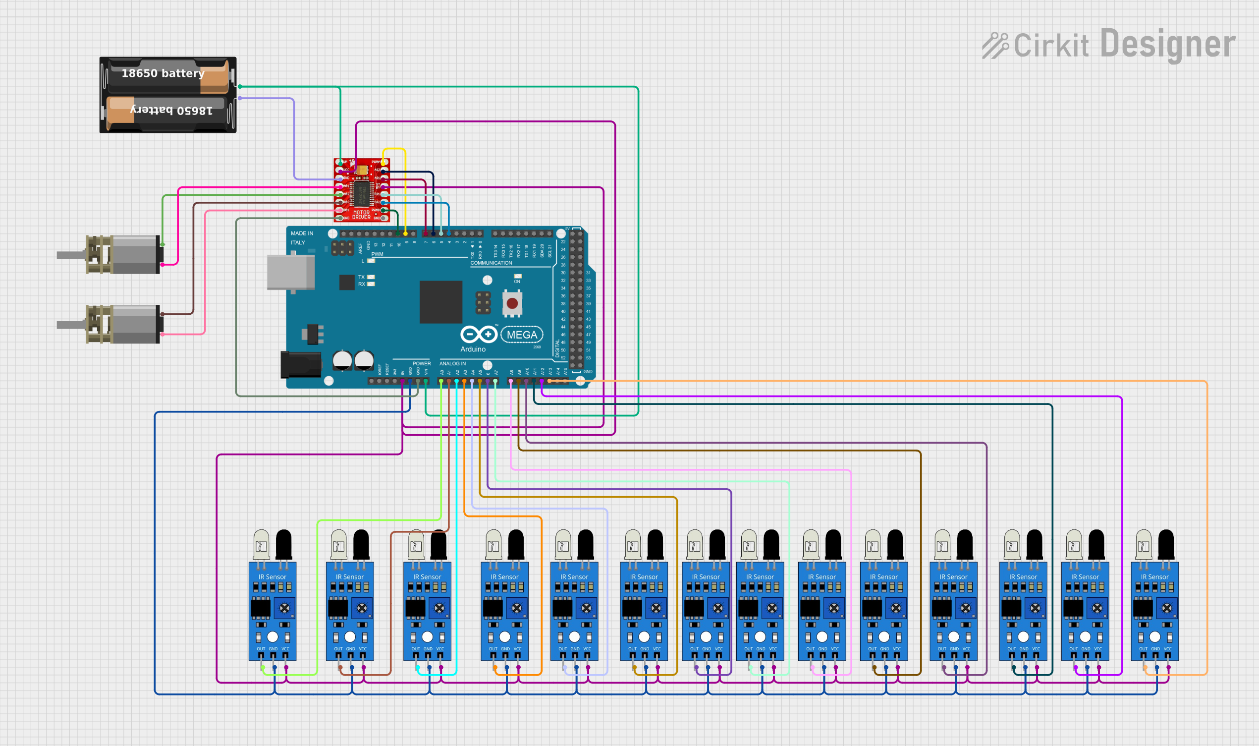
This circuit is designed to control two DC Mini Metal Gear Motors using a TB6612FNG Motor Driver, which is interfaced with an Arduino Mega 2560 microcontroller. The circuit also includes multiple IR sensors for input and a battery case to provide power. The Arduino Mega 2560 is responsible for processing the signals from the IR sensors and controlling the motor driver, which in turn controls the speed and direction of the motors.
Component List
TB6612FNG Motor Driver
- Description: A motor driver capable of driving two DC motors.
- Pins: GND, B01, B02, A02, A01, VCC, VM, PWMB, BI2, BI1, STBY, AI1, AI2, PWMA
DC Mini Metal Gear Motor (x2)
- Description: A compact and powerful DC motor with a gearbox for torque.
- Pins: IN1, IN2
My battery case
- Description: A case that holds batteries to provide power to the circuit.
- Pins: +, -
Arduino Mega 2560
- Description: A microcontroller board based on the ATmega2560.
- Pins: IOREF, RESET, 3V3, 5V, GND, VIN, A0-A15, D0-D53, AREF, SDA, SCL
IR Sensor (x12)
- Description: An infrared sensor used for detecting objects or motion.
- Pins: out, gnd, vcc
Wiring Details
TB6612FNG Motor Driver
- GND connected to Arduino Mega 2560 GND
- B01 connected to DC Mini Metal Gear Motor IN1
- B02 connected to DC Mini Metal Gear Motor IN2
- A02 connected to DC Mini Metal Gear Motor IN2
- A01 connected to DC Mini Metal Gear Motor IN1
- VCC connected to Arduino Mega 2560 5V
- VM connected to My battery case +
- PWMB connected to Arduino Mega 2560 D10 PWM
- BI2 connected to Arduino Mega 2560 D4 PWM
- BI1 connected to Arduino Mega 2560 D5 PWM
- STBY connected to Arduino Mega 2560 5V
- AI1 connected to Arduino Mega 2560 D7 PWM
- AI2 connected to Arduino Mega 2560 D6 PWM
- PWMA connected to Arduino Mega 2560 D9 PWM
DC Mini Metal Gear Motor
- IN1 and IN2 connected to TB6612FNG Motor Driver B01, B02, A01, A02 respectively
My battery case
-
- connected to Arduino Mega 2560 VIN and TB6612FNG Motor Driver VM
-
- connected to TB6612FNG Motor Driver GND
Arduino Mega 2560
- GND connected to TB6612FNG Motor Driver GND and all IR sensors gnd
- 5V connected to all IR sensors vcc
- VIN connected to My battery case +
- D10 PWM connected to TB6612FNG Motor Driver PWMB
- D4 PWM connected to TB6612FNG Motor Driver BI2
- D5 PWM connected to TB6612FNG Motor Driver BI1
- D7 PWM connected to TB6612FNG Motor Driver AI1
- D6 PWM connected to TB6612FNG Motor Driver AI2
- D9 PWM connected to TB6612FNG Motor Driver PWMA
- A0-A13 connected to IR sensors out
IR Sensors
- out connected to Arduino Mega 2560 A0-A13 (one sensor per pin)
- gnd connected to Arduino Mega 2560 GND
- vcc connected to Arduino Mega 2560 5V
Documented Code
Arduino Mega 2560 Code (sketch.ino)
void setup() {
  // put your setup code here, to run once:

}

void loop() {
  // put your main code here, to run repeatedly:

}
This code is a template for the Arduino Mega 2560. The setup() function is called once when the microcontroller is reset or powered on, and the loop() function is called repeatedly, allowing the microcontroller to perform operations based on the inputs from the IR sensors and control the motor driver accordingly. The actual implementation details would be added to these functions based on the specific requirements of the circuit's application.