
ESP32 and GPS Module-Based Battery-Powered Water Level Monitoring System
View and Edit Project In Cirkit Designer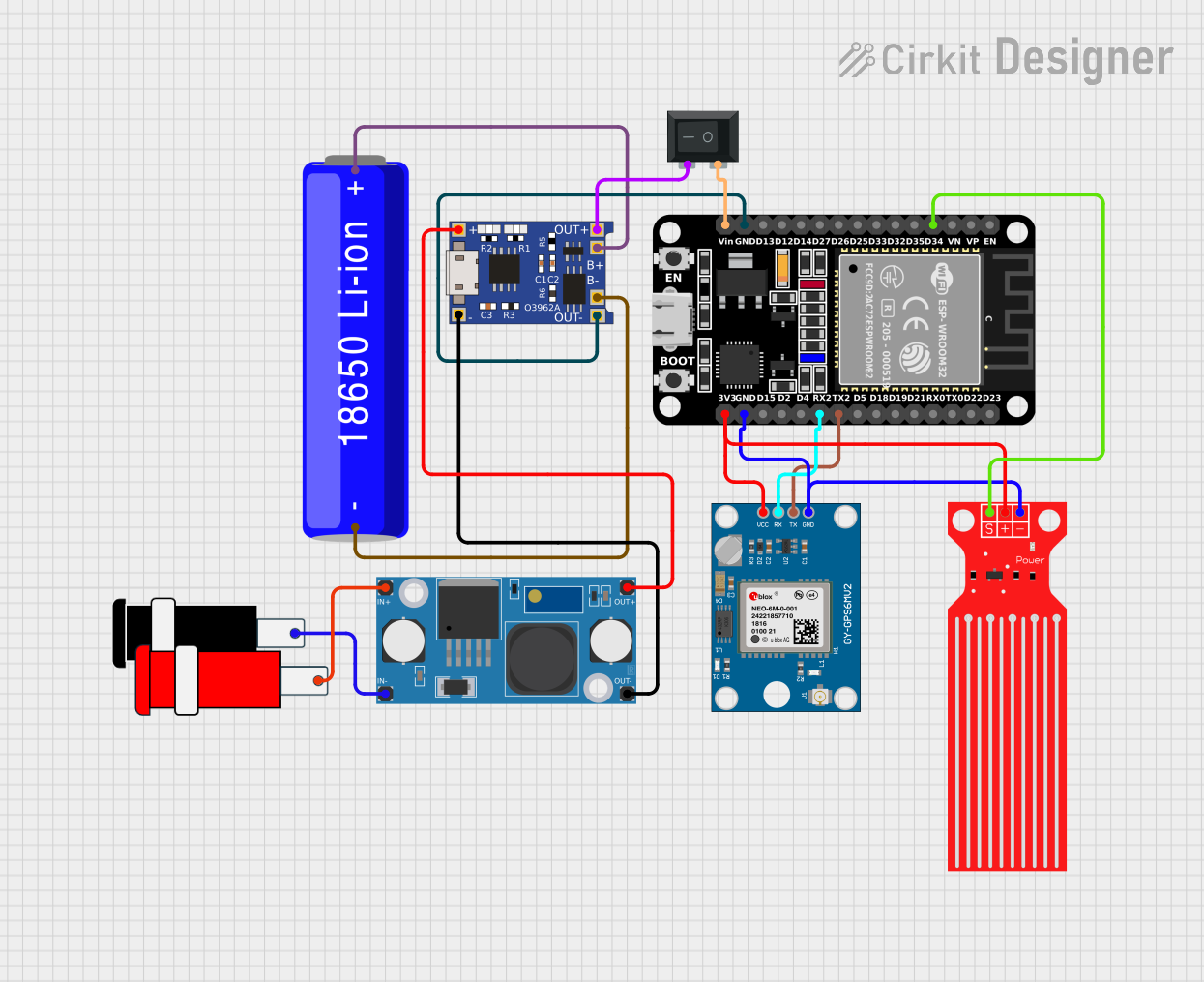
Circuit Documentation
Summary
This circuit is designed to interface an ESP32 microcontroller with a Neo 6M GPS module and a water level sensor. The circuit is powered by a 18650 Li-ion battery, which is managed by a TP4056 charging module and a LM2596 step-down module. A rocker switch is used to control the power to the ESP32. The ESP32 reads data from the GPS module and the water level sensor and outputs the data via serial communication.
Component List
ESP32 (30 pin)
- Description: A powerful microcontroller with built-in Wi-Fi and Bluetooth capabilities.
- Pins: EN, VP, VN, D34, D35, D32, D33, D25, D26, D27, D14, D12, D13, GND, Vin, D23, D22, TX0, RX0, D21, D19, D18, D5, TX2, RX2, D4, D2, D15, 3V3
Neo 6M GPS Module
- Description: A GPS module used for obtaining location data.
- Pins: GND, TX, RX, VCC
18650 Li-ion Battery
- Description: A rechargeable lithium-ion battery.
- Pins: -, +
Rocker Switch (SPST)
- Description: A single-pole single-throw switch used to control power.
- Pins: 1, 2
Water Level Sensor
- Description: A sensor used to detect the level of water.
- Pins: SIG, VCC, GND
TP4056
- Description: A lithium battery charger module.
- Pins: OUT-, B-, B+, OUT+, IN-, IN+
Connector 5V
- Description: A connector for 5V power supply.
- Pins: GND, VCC
LM2596 Step Down Module
- Description: A step-down voltage regulator module.
- Pins: OUT-, OUT+, IN-, IN+
Wiring Details
ESP32 (30 pin)
- D34: Connected to Water Level Sensor SIG
- GND: Connected to TP4056 OUT-, Water Level Sensor GND, Neo 6M GPS Module GND
- Vin: Connected to Rocker Switch 1
- TX2: Connected to Neo 6M GPS Module TX
- RX2: Connected to Neo 6M GPS Module RX
- 3V3: Connected to Water Level Sensor VCC, Neo 6M GPS Module VCC
Neo 6M GPS Module
- GND: Connected to ESP32 GND
- TX: Connected to ESP32 TX2
- RX: Connected to ESP32 RX2
- VCC: Connected to ESP32 3V3
18650 Li-ion Battery
- -: Connected to TP4056 B-
- +: Connected to TP4056 B+
Rocker Switch (SPST)
- 1: Connected to ESP32 Vin
- 2: Connected to TP4056 OUT+
Water Level Sensor
- SIG: Connected to ESP32 D34
- VCC: Connected to ESP32 3V3
- GND: Connected to ESP32 GND
TP4056
- OUT-: Connected to ESP32 GND
- B-: Connected to 18650 Li-ion Battery -
- B+: Connected to 18650 Li-ion Battery +
- OUT+: Connected to Rocker Switch 2
- IN-: Connected to LM2596 Step Down Module OUT-
- IN+: Connected to LM2596 Step Down Module OUT+
Connector 5V
- GND: Connected to LM2596 Step Down Module IN-
- VCC: Connected to LM2596 Step Down Module IN+
LM2596 Step Down Module
- OUT-: Connected to TP4056 IN-
- OUT+: Connected to TP4056 IN+
- IN-: Connected to Connector 5V GND
- IN+: Connected to Connector 5V VCC
Documented Code
#include <TinyGPS++.h>
#include <TinyGPSPlus.h>

#define GPS_BAUDRATE 9600  // The default baudrate of NEO-6M is 9600

TinyGPSPlus gps;  // the TinyGPS++ object

void setup() {
  Serial.begin(9600);
  Serial2.begin(GPS_BAUDRATE); // serial2 for GPS UART

  Serial.println(F("ESP32 - GPS module_Simulation"));
}

void loop() {
  if (Serial2.available() > 0) {
    if (gps.encode(Serial2.read())) {
      if (gps.location.isValid()) {
        Serial.print(F("Latitude: "));
        Serial.println(gps.location.lat(), 6);

        Serial.print(F("Longitude: "));
        Serial.println(gps.location.lng(), 6);

        Serial.print(F("Altitude: "));
        if (gps.altitude.isValid())
          Serial.println(gps.altitude.meters());
        else
          Serial.println(F("INVALID"));
      } else {
        Serial.println(F("Location: INVALID"));
      }

      Serial.print(F("Speed: "));
      if (gps.speed.isValid()) {
        Serial.print(gps.speed.kmph());
        Serial.println(F(" km/h"));
      } else {
        Serial.println(F("INVALID"));
      }

      Serial.print(F("GPS date&time: "));
      if (gps.date.isValid() && gps.time.isValid()) {
        Serial.print(gps.date.year());
        Serial.print(F("-"));
        Serial.print(gps.date.month());
        Serial.print(F("-"));
        Serial.print(gps.date.day());
        Serial.print(F(" "));
        Serial.print(gps.time.hour());
        Serial.print(F(":"));
        Serial.print(gps.time.minute());
        Serial.print(F(":"));
        Serial.println(gps.time.second());
      } else {
        Serial.println(F("INVALID"));
      }

      Serial.println();
    }
  }

  if (millis() > 5000 && gps.charsProcessed() < 10)
    Serial.println(F("No GPS data received: check wiring"));
}
This code initializes the ESP32 to read data from the Neo 6M GPS module and print the location, speed, and date/time information to the serial monitor. The code uses the TinyGPS++ library to parse the GPS data.