Cirkit Designer
Your all-in-one circuit design IDE
Home /
Project Documentation
Battery-Powered Adjustable Voltage Regulator with Power Jack

Circuit Documentation
Summary
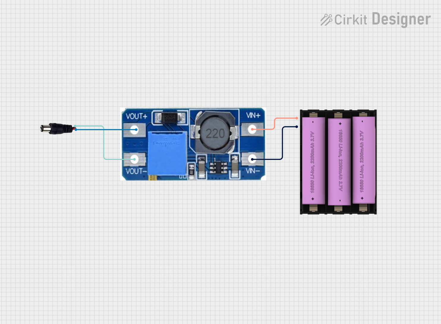
This circuit consists of a battery, a step-up boost power converter, and a power jack. The battery provides a 7V input which is then boosted by the power converter to a higher voltage. The boosted voltage is then supplied to the power jack.
Component List
Set Battery (7V)
- Description: A 7V battery used as the power source for the circuit.
- Pins: +, -
Step Up Boost Power Converter, Adjustable Voltage Regulator
- Description: A power converter that steps up the input voltage to a higher, adjustable output voltage.
- Pins: VOUT+, VOUT-, VIN+, VIN-
Power Jack
- Description: A power jack to provide the boosted voltage to an external device.
- Pins: POSITIF, NEGATIF
Wiring Details
Set Battery (7V)
- Pin + is connected to VIN+ of the Step Up Boost Power Converter.
- Pin - is connected to VIN- of the Step Up Boost Power Converter.
Step Up Boost Power Converter, Adjustable Voltage Regulator
- Pin VIN+ is connected to + of the Set Battery.
- Pin VIN- is connected to - of the Set Battery.
- Pin VOUT+ is connected to POSITIF of the Power Jack.
- Pin VOUT- is connected to NEGATIF of the Power Jack.
Power Jack
- Pin POSITIF is connected to VOUT+ of the Step Up Boost Power Converter.
- Pin NEGATIF is connected to VOUT- of the Step Up Boost Power Converter.
Code
There is no microcontroller code associated with this circuit.