
Arduino UNO Controlled Rain Sensor and Motor Driver System with Relay Switching
View and Edit Project In Cirkit Designer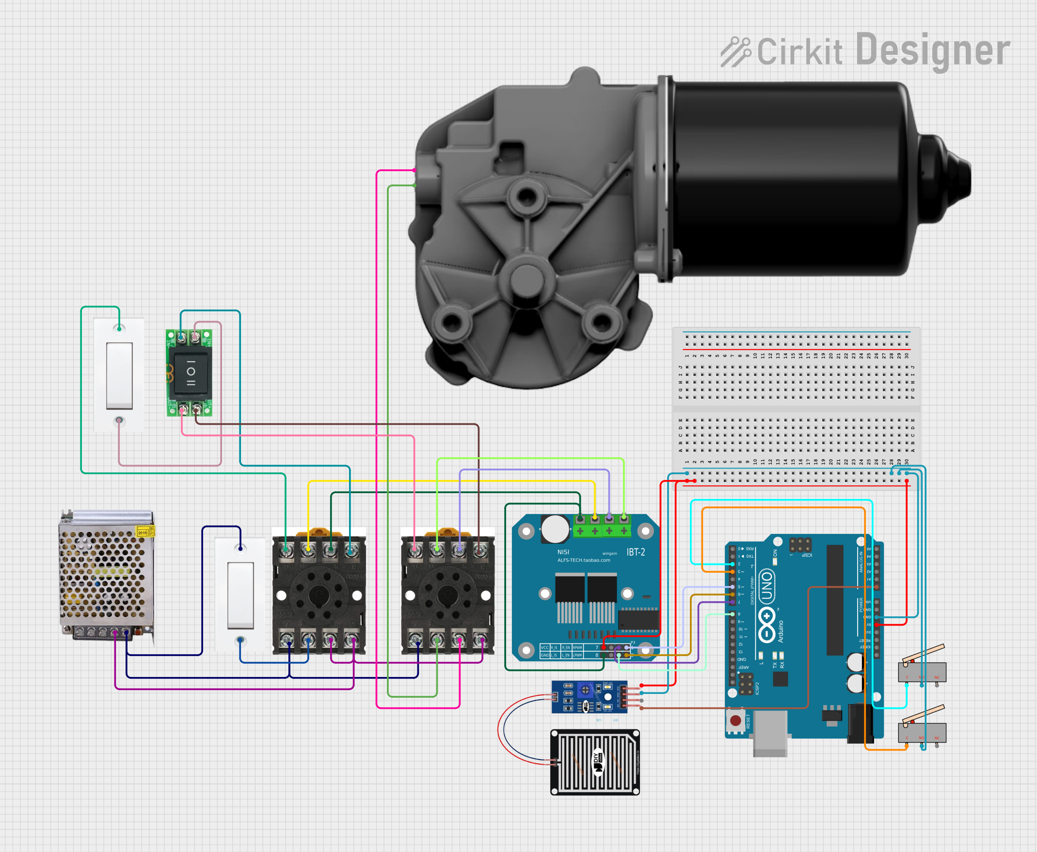
Circuit Documentation
Summary
This document provides a detailed overview of a circuit designed to interface various components with an Arduino UNO microcontroller. The circuit includes a power supply, relay modules, limit switches, a motor driver, a rain sensor, flush switches, a motor switch for direction control, and a DC worm gear motor. The Arduino UNO serves as the central processing unit, controlling the motor driver, reading sensor inputs, and managing the state of the relays and switches.
Component List
Arduino UNO
- Microcontroller board based on the ATmega328P
- It has 14 digital input/output pins, 6 analog inputs, a 16 MHz quartz crystal, a USB connection, a power jack, an ICSP header, and a reset button.
POWER SUPPLY 12V 5AMP
- Provides a 12V DC output with a maximum current of 5A.
- It has an input for 220V AC and outputs for ground and 12V-24V DC.
Relay 8 Pin (x2)
- An electromechanical switch that can be controlled by the Arduino to handle higher power circuits.
- Each relay has 8 pins for control and switching purposes.
Limit Switch (x2)
- A switch that is actuated by the motion of a machine part or presence of an object.
- It has a common (C), normally open (NO), and normally closed (NC) contact.
BTS7960 Motor Driver
- A high-power motor driver capable of driving high current loads.
- It has multiple control and power pins for interfacing with the Arduino and the motor.
Rain Sensor
- A sensor that detects the presence of water to determine if it is raining.
- It has analog output (AO), digital output (DO), ground (GRD), and power (VCC) pins.
Flush Switch (x2)
- A simple on/off switch that can be used to control power to a circuit.
- It has ground (GND) and power (VCC) pins.
DC Worm Gear Motor
- A type of DC motor coupled with a worm gear to reduce speed and increase torque.
- It has two terminals for power connection: Motor+ and Motor-.
Motor Switch Reverse Stop Forward
- A switch designed to control the direction of a motor, allowing it to move forward, reverse, or stop.
- It has input (IN+ and IN-) and output (OUT+ and OUT-) terminals for controlling motor direction.
Wiring Details
Arduino UNO
- 5V: Connected to the VCC of the Rain Sensor and Pin 5 of the BTS7960 Motor Driver.
- GND: Connected to the GRD of the Rain Sensor and NO of both Limit Switches.
- A0: Connected to the AO of the Rain Sensor.
- D8: Connected to Pin 3 of the BTS7960 Motor Driver.
- D7: Connected to Pin 7 of the BTS7960 Motor Driver.
- D6: Connected to Pin 4 of the BTS7960 Motor Driver.
- D5: Connected to Pin 8 of the BTS7960 Motor Driver.
- D3: Connected to the C of the first Limit Switch.
- D2: Connected to the C of the second Limit Switch.
POWER SUPPLY 12V 5AMP
- GND (DC): Connected to pins 2 and 1 of both Relay 8 Pin modules.
- 12V-24V Output (DC): Connected to pin 7 of both Relay 8 Pin modules and VCC of the first Flush Switch.
Relay 8 Pin
Pin 2 (First Relay): Connected to GND (DC) of the Power Supply.
Pin 1 (First Relay): Connected to GND (DC) of the Power Supply.
Pin 7 (First Relay): Connected to 12V-24V Output (DC) of the Power Supply and VCC of the first Flush Switch.
Pin 6 (First Relay): Connected to VCC of the second Flush Switch.
Pin 5 (First Relay): Connected to Pin 11 of the BTS7960 Motor Driver.
Pin 4 (First Relay): Connected to Pins 1 and 12 of the BTS7960 Motor Driver.
Pin 3 (First Relay): Connected to IN- of the Motor Switch Reverse Stop Forward.
Pin 8 (First Relay): Connected to GND of the first Flush Switch.
Pin 2 (Second Relay): Connected to GND (DC) of the Power Supply.
Pin 1 (Second Relay): Connected to Motor+ of the DC Worm Gear Motor.
Pin 7 (Second Relay): Connected to 12V-24V Output (DC) of the Power Supply and VCC of the first Flush Switch.
Pin 6 (Second Relay): Connected to OUT- of the Motor Switch Reverse Stop Forward.
Pin 5 (Second Relay): Connected to Pin 9 of the BTS7960 Motor Driver.
Pin 4 (Second Relay): Connected to Pin 10 of the BTS7960 Motor Driver.
Pin 3 (Second Relay): Connected to OUT+ of the Motor Switch Reverse Stop Forward.
Pin 8 (Second Relay): Connected to Motor- of the DC Worm Gear Motor.
Limit Switches
NO (First Limit Switch): Connected to GRD of the Rain Sensor.
C (First Limit Switch): Connected to D3 of the Arduino UNO.
NO (Second Limit Switch): Connected to GRD of the Rain Sensor.
C (Second Limit Switch): Connected to D2 of the Arduino UNO.
BTS7960 Motor Driver
- Pin 5: Connected to 5V of the Arduino UNO.
- Pin 3: Connected to D8 of the Arduino UNO.
- Pin 7: Connected to D7 of the Arduino UNO.
- Pin 4: Connected to D6 of the Arduino UNO.
- Pin 8: Connected to D5 of the Arduino UNO.
- Pin 11: Connected to Pin 5 of the first Relay 8 Pin.
- Pin 1 and Pin 12: Connected to Pin 4 of the first Relay 8 Pin.
- Pin 9: Connected to Pin 5 of the second Relay 8 Pin.
- Pin 10: Connected to Pin 4 of the second Relay 8 Pin.
Rain Sensor
- VCC: Connected to 5V of the Arduino UNO.
- GRD: Connected to GND of the Arduino UNO and NO of both Limit Switches.
- AO: Connected to A0 of the Arduino UNO.
Flush Switches
VCC (First Flush Switch): Connected to 12V-24V Output (DC) of the Power Supply and Pin 7 of both Relay 8 Pin modules.
GND (First Flush Switch): Connected to Pin 8 of the first Relay 8 Pin.
VCC (Second Flush Switch): Connected to Pin 6 of the first Relay 8 Pin.
GND (Second Flush Switch): Connected to IN+ of the Motor Switch Reverse Stop Forward.
DC Worm Gear Motor
- Motor+: Connected to Pin 1 of the second Relay 8 Pin.
- Motor-: Connected to Pin 8 of the second Relay 8 Pin.
Motor Switch Reverse Stop Forward
- IN+: Connected to GND of the second Flush Switch.
- IN-: Connected to Pin 3 of the first Relay 8 Pin.
- OUT+: Connected to Pin 3 of the second Relay 8 Pin.
- OUT-: Connected to Pin 6 of the second Relay 8 Pin.
Documented Code
Arduino UNO Code (sketch.ino)
void setup() {
  // put your setup code here, to run once:

}

void loop() {
  // put your main code here, to run repeatedly:

}
Note: The provided code is a template and does not contain any functional code. It is expected that the user will fill in the setup and loop functions with the necessary code to control the circuit components as per the requirements of the project.