
Arduino Mega 2560-Based Autonomous Robot with GPS, Bluetooth, and Environmental Sensors
View and Edit Project In Cirkit Designer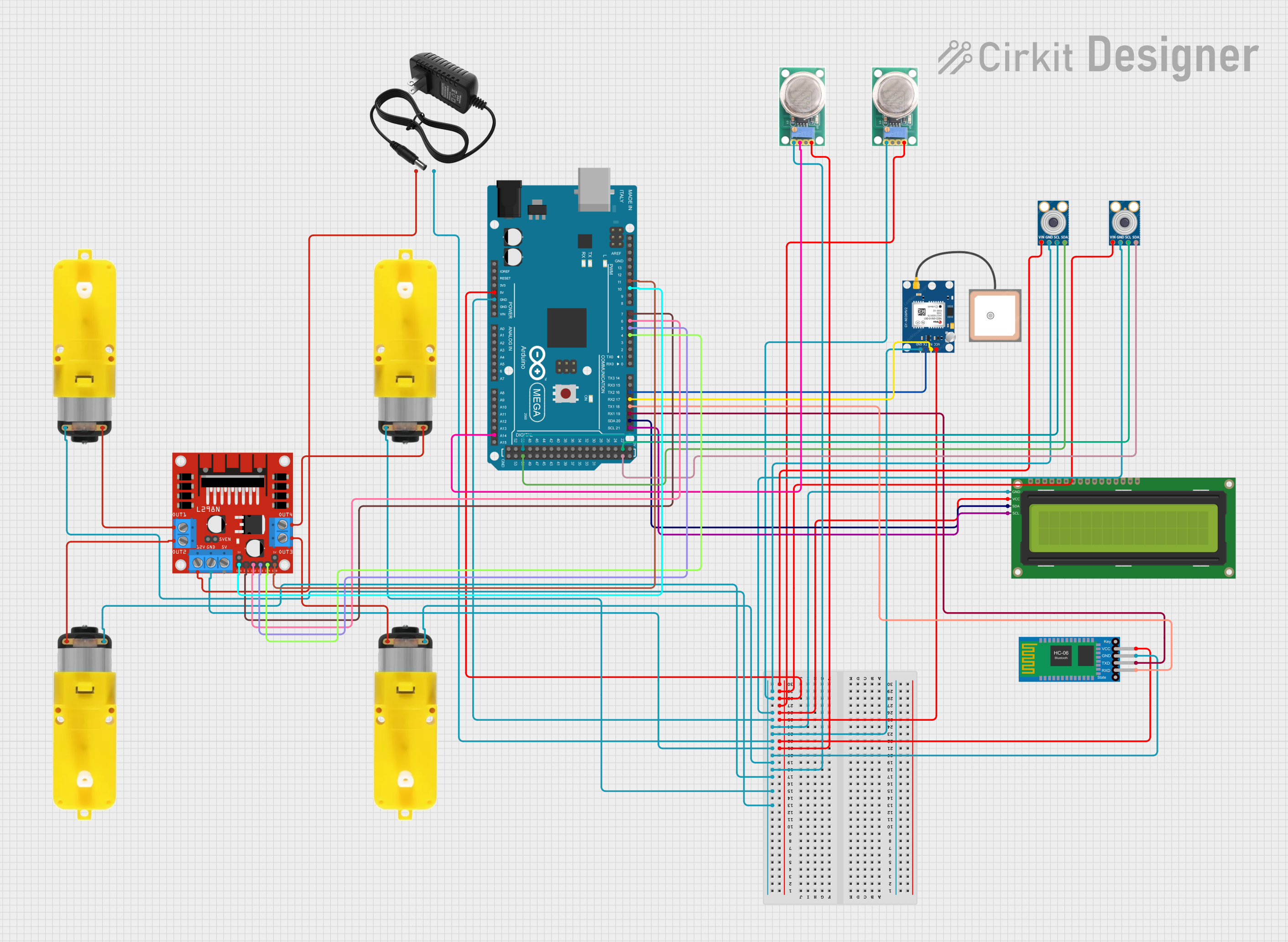
Circuit Documentation
Summary
This document provides a detailed overview of a circuit designed to control a robotic vehicle equipped with various sensors and communication modules. The circuit includes temperature sensors, gas sensors, a GPS module, a Bluetooth module, an LCD display, and a motor driver, all interfaced with an Arduino Mega 2560 microcontroller. The vehicle can detect human presence and gas levels, and it can be controlled via Bluetooth commands.
Component List
MLX90614 (Temperature Sensor)
- Pins: SDA, SCL, GND, VIN
- Description: Infrared temperature sensor used for non-contact temperature measurements.
MQ-136 (Gas Sensor)
- Pins: GND, OUT1, OUT2, VCC
- Description: Gas sensor used to detect the presence of gases.
12V Power Supply
- Pins: +, -
- Description: Provides 12V power to the circuit.
L298N DC Motor Driver
- Pins: OUT1, OUT2, 12V, GND, 5V, OUT3, OUT4, 5V-ENA-JMP-I, 5V-ENA-JMP-O, +5V-J1, +5V-J2, ENA, IN1, IN2, IN3, IN4, ENB
- Description: Motor driver used to control the motors of the vehicle.
GPS NEO 6M
- Pins: VCC, RX, TX, GND
- Description: GPS module used for location tracking.
16x2 I2C LCD
- Pins: GND, VCC, SDA, SCL
- Description: LCD display used to show sensor readings and status messages.
Bluetooth HC-06
- Pins: VCC, GND, TXD, RXD
- Description: Bluetooth module used for wireless communication.
Motor with Reducer
- Pins: 3 - 6 VCC, GND
- Description: DC motor with a reducer for driving the vehicle.
Arduino Mega 2560
- Pins: IOREF, RESET, 3V3, 5V, GND, VIN, A0-A15, D0-D53, AREF, SDA, SCL
- Description: Microcontroller used to control the entire circuit.
Wiring Details
MLX90614 (Temperature Sensor)
- SDA connected to Arduino Mega 2560 D51
- SCL connected to Arduino Mega 2560 D50
- GND connected to common ground
- VIN connected to Arduino Mega 2560 5V
MLX90614 (Temperature Sensor)
- SDA connected to Arduino Mega 2560 D23
- SCL connected to Arduino Mega 2560 D22
- GND connected to common ground
- VIN connected to Arduino Mega 2560 5V
MQ-136 (Gas Sensor)
- GND connected to common ground
- OUT1 connected to Arduino Mega 2560 A14
- OUT2 not connected
- VCC connected to Arduino Mega 2560 5V
MQ-136 (Gas Sensor)
- GND connected to common ground
- OUT1 not connected
- OUT2 not connected
- VCC connected to Arduino Mega 2560 5V
12V Power Supply
- + connected to L298N DC Motor Driver 12V
- - connected to common ground
L298N DC Motor Driver
- OUT1 connected to Motor with Reducer 3 - 6 VCC
- OUT2 connected to Motor with Reducer 3 - 6 VCC
- OUT3 connected to Motor with Reducer 3 - 6 VCC
- OUT4 connected to Motor with Reducer 3 - 6 VCC
- 12V connected to 12V Power Supply +
- GND connected to common ground
- 5V not connected
- 5V-ENA-JMP-I not connected
- 5V-ENA-JMP-O not connected
- +5V-J1 not connected
- +5V-J2 not connected
- ENA connected to Arduino Mega 2560 D10 PWM
- IN1 connected to Arduino Mega 2560 D7 PWM
- IN2 connected to Arduino Mega 2560 D6 PWM
- IN3 connected to Arduino Mega 2560 D5 PWM
- IN4 connected to Arduino Mega 2560 D4 PWM
- ENB connected to Arduino Mega 2560 D11 PWM
GPS NEO 6M
- VCC connected to Arduino Mega 2560 5V
- RX connected to Arduino Mega 2560 D17 PWM/RX2
- TX connected to Arduino Mega 2560 D16 PWM/TX2
- GND connected to common ground
16x2 I2C LCD
- GND connected to common ground
- VCC connected to Arduino Mega 2560 5V
- SDA connected to Arduino Mega 2560 D20/SDA
- SCL connected to Arduino Mega 2560 D21/SCL
Bluetooth HC-06
- VCC connected to Arduino Mega 2560 5V
- GND connected to common ground
- TXD connected to Arduino Mega 2560 D19/RX1
- RXD connected to Arduino Mega 2560 D18/TX1
Motor with Reducer
- 3 - 6 VCC connected to L298N DC Motor Driver OUT1
- GND connected to common ground
Motor with Reducer
- 3 - 6 VCC connected to L298N DC Motor Driver OUT2
- GND connected to common ground
Motor with Reducer
- 3 - 6 VCC connected to L298N DC Motor Driver OUT3
- GND connected to common ground
Motor with Reducer
- 3 - 6 VCC connected to L298N DC Motor Driver OUT4
- GND connected to common ground
Arduino Mega 2560
- GND connected to common ground
- 5V connected to various components as described above
- D51 connected to MLX90614 SDA
- D50 connected to MLX90614 SCL
- D23 connected to MLX90614 SDA
- D22 connected to MLX90614 SCL
- A14 connected to MQ-136 OUT1
- D21/SCL connected to 16x2 I2C LCD SCL
- D20/SDA connected to 16x2 I2C LCD SDA
- D19/RX1 connected to Bluetooth HC-06 TXD
- D18/TX1 connected to Bluetooth HC-06 RXD
- D17 PWM/RX2 connected to GPS NEO 6M RX
- D16 PWM/TX2 connected to GPS NEO 6M TX
- D10 PWM connected to L298N DC Motor Driver ENA
- D11 PWM connected to L298N DC Motor Driver ENB
- D7 PWM connected to L298N DC Motor Driver IN1
- D6 PWM connected to L298N DC Motor Driver IN2
- D5 PWM connected to L298N DC Motor Driver IN3
- D4 PWM connected to L298N DC Motor Driver IN4
Documented Code
#include <Wire.h>
#include <SoftwareWire.h>
#include <LiquidCrystal_I2C.h>
#include <TinyGPS++.h>

// Define I2C addresses for MLX90614 sensors
#define MLX1_ADDRESS 0x5A
#define MLX2_ADDRESS 0x5A // Both sensors have the same default address

// I2C instances for MLX90614 sensors (using different buses)
SoftwareWire Wire1(51, 50); // SDA = 23, SCL = 22 for Sensor 1
SoftwareWire Wire2(25, 24); // SDA = 25, SCL = 24 for Sensor 2

// LCD setup (8x16 LCD)
LiquidCrystal_I2C lcd(0x27, 16, 2);

// GPS setup
TinyGPSPlus gps;
HardwareSerial& gpsSerial = Serial2; // Using Serial2 for GPS

// MQ-135 pins
#define MQ135_LEFT A15
#define MQ135_RIGHT A14

// Motor control pins
#define IN1 7
#define IN2 6
#define ENA 10    // Pin 10 for motor speed control
#define IN3 4
#define IN4 5
#define ENB 11

// Thresholds
#define TEMP_THRESHOLD 20.0  // Temperature threshold for human detection
#define GAS_THRESHOLD 20     // Threshold for gas sensor comparison