
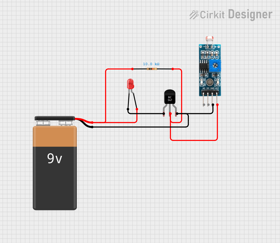
Circuit Documentation
Summary of the Circuit
This circuit appears to be a simple light-sensitive switch that uses a Light Dependent Resistor (LDR) to control the state of an LED. When the light level falling on the LDR is below a certain threshold, the LED is turned on. The circuit uses a 9V battery as the power source, a 10k Ohm resistor to limit current, an LDR as the light sensor, a BC547 transistor as a switch, and an LED as the indicator.
Component List
9V Battery
- Description: Provides the power supply for the circuit.
- Pins: Negative (-), Positive (+)
LED: Two Pin (red)
- Description: Emits light when current flows through it.
- Pins: Cathode, Anode
Resistor
- Description: Limits the current flowing through the LED.
- Value: 10,000 Ohms (10k Ohms)
Module LDR
- Description: Changes resistance based on the amount of light it receives.
- Pins: VCC, GND, DO (Digital Output), AO (Analog Output)
BC547 Transistor
- Description: Acts as a switch to control the flow of current through the LED.
- Pins: Collector, Base, Emitter
Wiring Details
9V Battery
- Negative (-) is connected to:
- GND of Module LDR
- Emitter of BC547 Transistor
- Positive (+) is connected to:
- Pin1 of Resistor
LED: Two Pin (red)
- Cathode is connected to:
- Collector of BC547 Transistor
- Anode is connected to:
- Pin1 of Resistor
Resistor
- Pin1 is connected to:
- Positive (+) of 9V Battery
- Anode of LED
- Pin2 is connected to:
- VCC of Module LDR
- Base of BC547 Transistor
Module LDR
- VCC is connected to:
- Pin2 of Resistor
- Base of BC547 Transistor
- GND is connected to:
- Negative (-) of 9V Battery
BC547 Transistor
- Collector is connected to:
- Cathode of LED
- Base is connected to:
- VCC of Module LDR
- Pin2 of Resistor
- Emitter is connected to:
- Negative (-) of 9V Battery
Documented Code
There is no embedded code provided for this circuit as there are no microcontrollers or programmable components listed in the provided parts list. The circuit operates purely on the basis of the electronic properties of the components used.