
Arduino Nano Controlled Robotic Vehicle with Wireless Joystick and Servo Steering
View and Edit Project In Cirkit Designer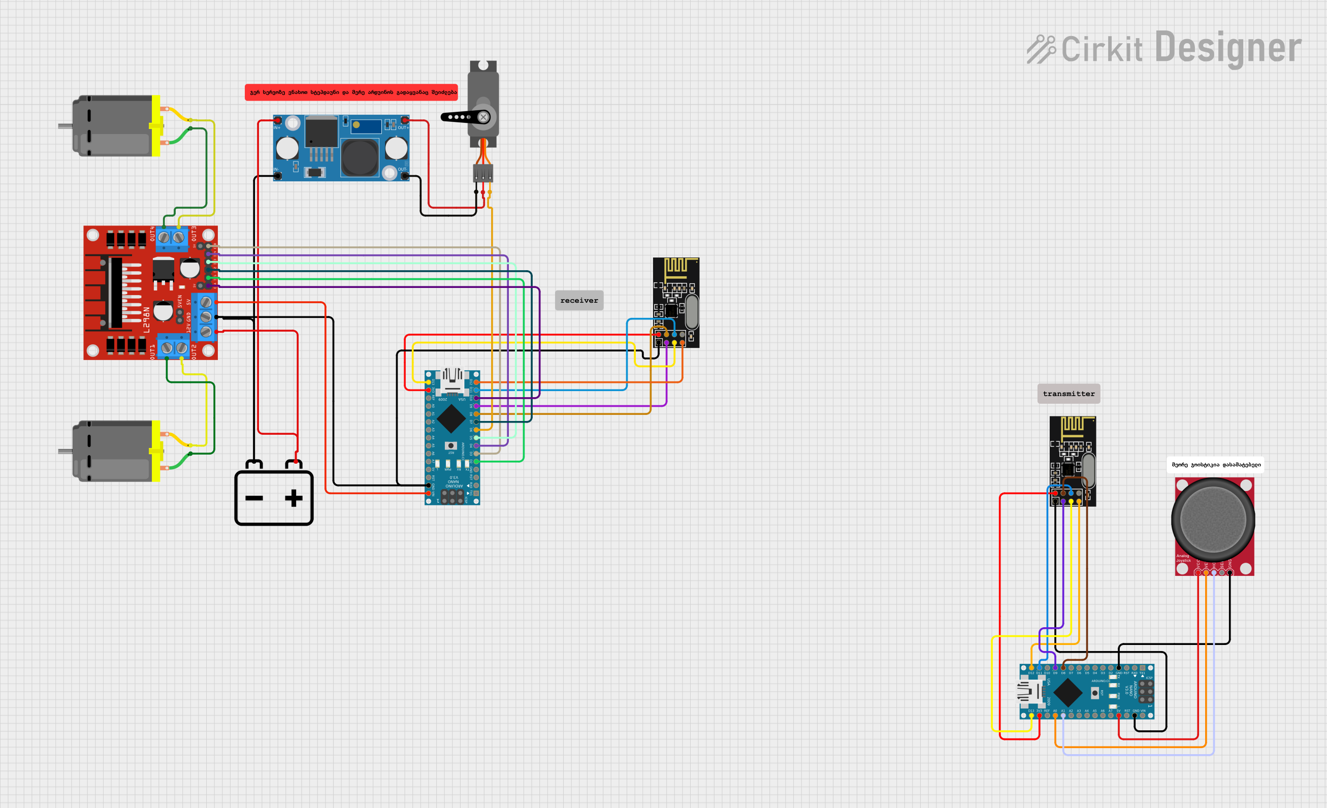
Circuit Documentation
Summary
This circuit is designed to remotely control a DC motor and a servo motor using two Arduino Nano microcontrollers and NRF24L01 wireless transceiver modules. The circuit includes a joystick for user input, a DC motor driver to manage the motor's direction and speed, and a step-down module to regulate the power supply. The first Arduino Nano acts as a transmitter, reading the joystick's position and sending the data wirelessly. The second Arduino Nano receives the data and controls the DC motor and servo motor accordingly.
Component List
Microcontrollers
- Arduino Nano: A compact microcontroller board based on the ATmega328P, featuring digital and analog I/O pins.
Communication Modules
- NRF24L01: A 2.4GHz wireless transceiver module used for short-range wireless communication.
Motors
- DC Motor: An electric motor that runs on direct current (DC) electricity.
- Servo: A rotary actuator or linear actuator that allows for precise control of angular or linear position.
Motor Driver
- L298N DC Motor Driver: A dual H-bridge motor driver that can control the speed and direction of two DC motors or one stepper motor.
Power Supply
- 12v Battery: A power source for the circuit.
- LM2596 Step Down Module: A voltage regulator that steps down the input voltage to a lower output voltage.
Input Devices
- Analog Joystick (Wokwi Compatible): A manual control input device with two axes of movement.
Wiring Details
Arduino Nano (Transmitter)
- D2: Connected to L298N DC motor driver IN1.
- D3: Connected to L298N DC motor driver ENB.
- D4: Connected to L298N DC motor driver IN4.
- D5: Connected to L298N DC motor driver IN3.
- D6: Connected to Servo PWM.
- D7: Connected to L298N DC motor driver IN2.
- D8: Connected to NRF24L01 CSN.
- D9: Connected to NRF24L01 CE.
- D10: Connected to L298N DC motor driver ENA.
- D11/MOSI: Connected to NRF24L01 MOSI.
- D12/MISO: Connected to NRF24L01 MISO.
- D13/SCK: Connected to NRF24L01 SCK.
- VIN: Connected to L298N DC motor driver 5V.
- 3V3: Connected to NRF24L01 VCC (3V).
- GND: Common ground with L298N DC motor driver, LM2596 Step Down Module, NRF24L01, and 12v Battery.
Arduino Nano (Receiver)
- D8: Connected to NRF24L01 CSN.
- D9: Connected to NRF24L01 CE.
- D11/MOSI: Connected to NRF24L01 MOSI.
- D12/MISO: Connected to NRF24L01 MISO.
- D13/SCK: Connected to NRF24L01 SCK.
- 5V: Connected to Analog Joystick VCC.
- A0: Connected to Analog Joystick VERT.
- A1: Connected to Analog Joystick HORZ.
- 3V3: Connected to NRF24L01 VCC (3V).
- GND: Common ground with Analog Joystick and NRF24L01.
L298N DC Motor Driver
- IN1, IN2, IN3, IN4: Control inputs from Arduino Nano (Transmitter).
- ENA, ENB: PWM control inputs from Arduino Nano (Transmitter).
- OUT1, OUT2, OUT3, OUT4: Outputs to DC Motors.
- 5V: Power input from Arduino Nano (Transmitter) VIN.
- 12V: Power input from LM2596 Step Down Module IN+ and 12v Battery +.
- GND: Common ground with LM2596 Step Down Module IN-, NRF24L01 GND, 12v Battery -, and Arduino Nano (Transmitter) GND.
NRF24L01 (Transmitter and Receiver)
- CSN: Chip Select Not input from Arduino Nano.
- CE: Chip Enable input from Arduino Nano.
- MOSI: Master Out Slave In data line connected to Arduino Nano MOSI.
- MISO: Master In Slave Out data line connected to Arduino Nano MISO.
- SCK: Serial Clock line connected to Arduino Nano SCK.
- VCC (3V): Power input from Arduino Nano 3V3.
- GND: Common ground with Arduino Nano.
Servo
- PWM: Pulse Width Modulation input from Arduino Nano (Transmitter) D6.
- VCC: Power input from LM2596 Step Down Module OUT+.
- GND: Common ground with LM2596 Step Down Module OUT-.
LM2596 Step Down Module
- IN+: Power input from 12v Battery +.
- IN-: Common ground with L298N DC motor driver GND, NRF24L01 GND, 12v Battery -, and Arduino Nano (Transmitter) GND.
- OUT+: Power output to Servo VCC.
- OUT-: Common ground with Servo GND.
Analog Joystick (Wokwi Compatible)
- VCC: Power input from Arduino Nano (Receiver) 5V.
- VERT: Vertical axis output to Arduino Nano (Receiver) A0.
- HORZ: Horizontal axis output to Arduino Nano (Receiver) A1.
- GND: Common ground with Arduino Nano (Receiver).
Documented Code
Transmitter Code (Arduino Nano)
//transmitter
// Library: TMRh20/RF24 (https://github.com/tmrh20/RF24/)
#include <SPI.h>
#include <RF24.h>
#include <nRF24L01.h>

RF24 radio(9, 8); // CE, CSN
const byte address[10] = "ADDRESS01";

int joyX = A0; // Joystick X-axis connected to analog pin A0
int joyY = A1; // Joystick Y-axis connected to analog pin A1

struct DataPackage {
  int x;
  int y;
};
DataPackage data;

void setup() {
  Serial.begin(9600);
  radio.begin();
  radio.openWritingPipe(address);
  radio.setPALevel(RF24_PA_MIN);
  radio.stopListening();
  pinMode(joyX, INPUT);
  pinMode(joyY, INPUT);
}

void loop() {
  data.x = analogRead(joyX);  // Read X-axis value
  data.y = analogRead(joyY);  // Read Y-axis value
  radio.write(&data, sizeof(data));

  // Print joystick data for debugging
  Serial.print("X: ");
  Serial.print(data.x);
  Serial.print(" | Y: ");
  Serial.println(data.y);

  delay(100); // Adjust delay as needed
}
Receiver Code (Arduino Nano)
// Libraries for RF24 and Servo control
#include <SPI.h>
#include <RF24.h>
#include <nRF24L01.h>
#include <Servo.h>

RF24 radio(9, 8); // CE, CSN
const byte address[10] = "ADDRESS01";

const int motorPin1 = 3;   // Pin to control first DC motor (PWM-capable)
const int motorPin2 = 10;   // Pin to control second DC motor (PWM-capable)
const int motorDirPin1 = 4; // Direction control pin for first motor
const int motorDirPin2 = 7; // Direction control pin for second motor
const int servoPin = 6;    // Pin to control servo

Servo myServo;          // Servo motor object
int motorSpeed1 = 0;    // Speed of the first DC motor
int motorSpeed2 = 0;    // Speed of the second DC motor

struct DataPackage {
  int x;
  int y;
};
DataPackage data;

void setup() {
  Serial.begin(9600);
  radio.begin();
  radio.openReadingPipe(0, address);
  radio.setPALevel(RF24_PA_MIN);
  radio.startListening();

  myServo.attach(servoPin); // Attach servo to the specified pin
  pinMode(motorPin1, OUTPUT);
  pinMode(motorPin2, OUTPUT);
  pinMode(motorDirPin1, OUTPUT);
  pinMode(motorDirPin2, OUTPUT);
}

void loop() {
  if (radio.available()) {
    radio.read(&data, sizeof(data));

    // Map joystick Y-axis to motor speeds
    motorSpeed1 = map(data.y, 0, 1023, -255, 255);
    motorSpeed2 = map(data.y, 0, 1023, -255, 255);

    int motorDirection1 = (motorSpeed1 >= 0) ? HIGH : LOW;
    int motorDirection2 = (motorSpeed2 >= 0) ? HIGH : LOW;

    digitalWrite(motorDirPin1, motorDirection1);
    digitalWrite(motorDirPin2, motorDirection2);

    analogWrite(motorPin1, abs(motorSpeed1));
    analogWrite(motorPin