
Arduino UNO Ultrasonic Distance Sensor with LED and Buzzer Alert
View and Edit Project In Cirkit Designer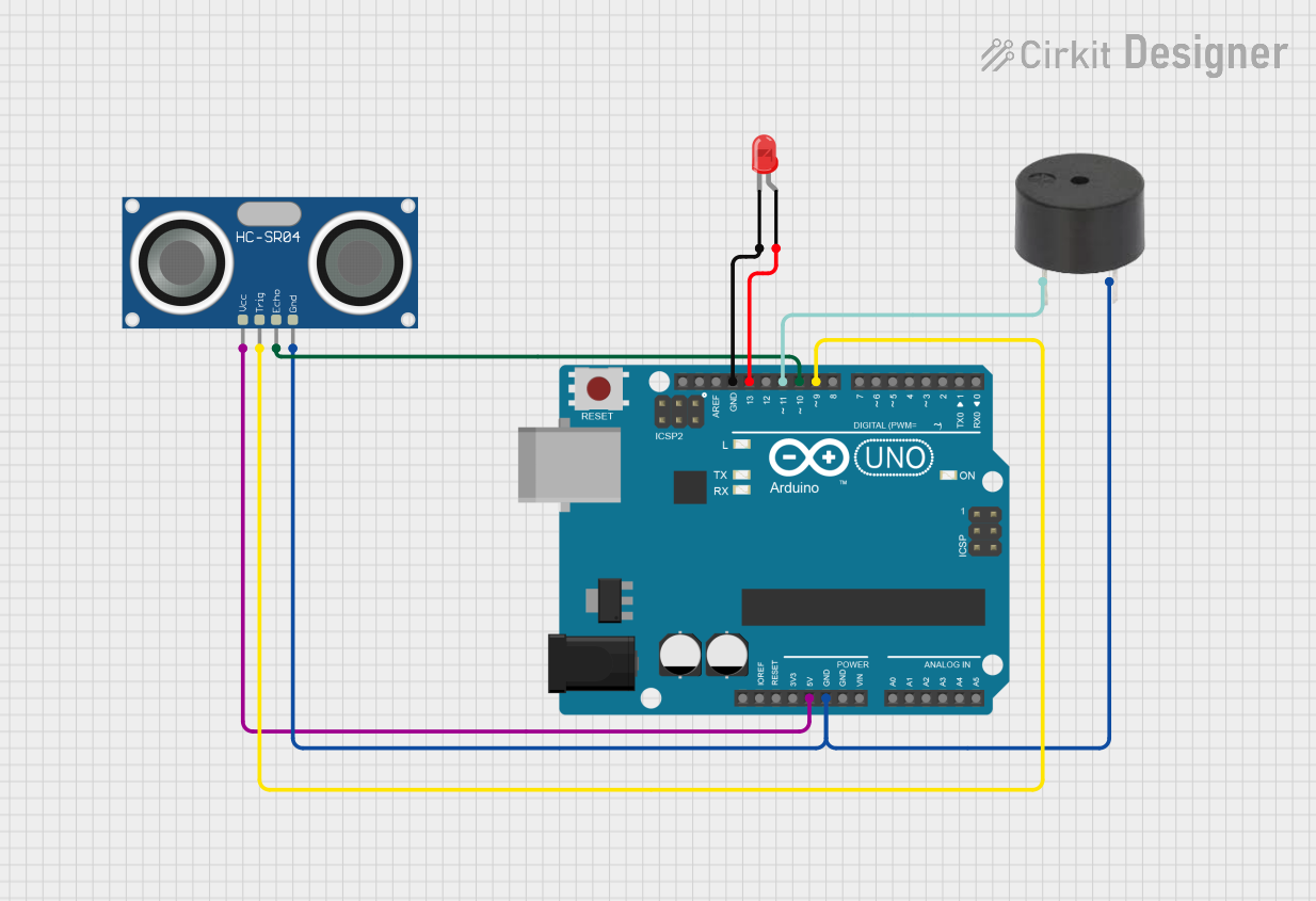
Circuit Documentation
Summary
This circuit consists of an Arduino UNO microcontroller, an HC-SR04 Ultrasonic Sensor, a red LED, and a buzzer. The Arduino UNO serves as the central control unit, interfacing with the ultrasonic sensor to measure distance, and using the LED and buzzer to provide visual and auditory feedback.
Component List
Arduino UNO
- Description: A microcontroller board based on the ATmega328P.
- Pins: UNUSED, IOREF, Reset, 3.3V, 5V, GND, Vin, A0, A1, A2, A3, A4, A5, SCL, SDA, AREF, D13, D12, D11, D10, D9, D8, D7, D6, D5, D4, D3, D2, D1, D0
HC-SR04 Ultrasonic Sensor
- Description: A sensor used to measure distance by using ultrasonic waves.
- Pins: VCC, TRIG, ECHO, GND
LED: Two Pin (red)
- Description: A red light-emitting diode used for visual indication.
- Pins: cathode, anode
Buzzer
- Description: An electronic device that emits sound when powered.
- Pins: PIN, GND
Wiring Details
Arduino UNO
- 5V: Connected to VCC of HC-SR04 Ultrasonic Sensor
- GND: Connected to GND of HC-SR04 Ultrasonic Sensor, GND of buzzer, and cathode of LED
- D13: Connected to anode of LED
- D11: Connected to PIN of buzzer
- D10: Connected to ECHO of HC-SR04 Ultrasonic Sensor
- D9: Connected to TRIG of HC-SR04 Ultrasonic Sensor
HC-SR04 Ultrasonic Sensor
- VCC: Connected to 5V of Arduino UNO
- GND: Connected to GND of Arduino UNO
- ECHO: Connected to D10 of Arduino UNO
- TRIG: Connected to D9 of Arduino UNO
LED: Two Pin (red)
- cathode: Connected to GND of Arduino UNO
- anode: Connected to D13 of Arduino UNO
Buzzer
- PIN: Connected to D11 of Arduino UNO
- GND: Connected to GND of Arduino UNO
Code Documentation
Arduino UNO Code
sketch.ino
void setup() {
  // put your setup code here, to run once:

}

void loop() {
  // put your main code here, to run repeatedly:

}
documentation.txt