
Arduino Mega 2560 Controlled Dual DC Motor System with Sensor Feedback and OLED Display
View and Edit Project In Cirkit Designer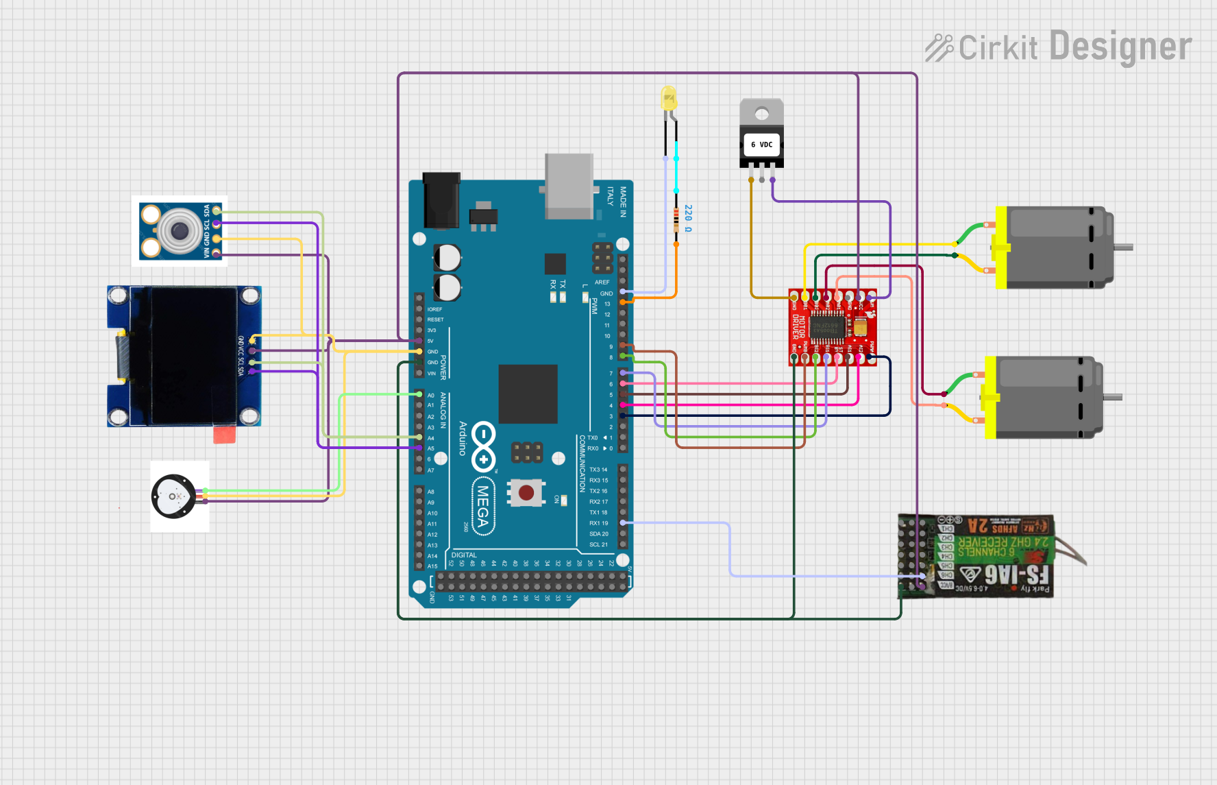
Circuit Documentation
Summary
This circuit is designed to control two DC motors using an Arduino Mega 2560 microcontroller and a TB6612FNG Motor Driver. It includes an OLED display and a pulse sensor for user interface and feedback, as well as a temperature sensor (MLX90614) for measuring temperature. The circuit is powered by a voltage regulator that ensures a stable voltage supply to the motor driver. A yellow LED with a resistor is included for status indication. The FLYSKY FS-IA6 receiver is interfaced with the Arduino for potential remote control capabilities.
Component List
Microcontroller
- Arduino Mega 2560: A microcontroller board based on the ATmega2560 with numerous digital and analog I/O pins.
Motors
- DC Motor: Two motors that convert electrical energy into mechanical rotation.
Motor Driver
- TB6612FNG Motor Driver: A driver module that allows for control of two DC motors, providing options for speed and direction control.
Power Management
- Voltage Regulator: A device that maintains a constant voltage level to the motor driver.
Sensors
- PULSE SENSOR: A sensor used to detect heart rate.
- MLX90614: An infrared thermometer for non-contact temperature measurements.
Communication
- FLYSKY FS- IA6: A 6-channel receiver for remote control applications.
Display
- OLED 1.3": A small display for outputting data such as sensor readings or system status.
Indicators
- LED: Two Pin (yellow): An indicator light, typically used for status indication.
- Resistor: A 220 Ohm resistor used to limit current to the LED.
Wiring Details
Arduino Mega 2560
- 5V connected to OLED VCC, FLYSKY VCC, MLX90614, TB6612FNG VCC, and PULSE SENSOR.
- GND connected to OLED GND, MLX90614, PULSE SENSOR, TB6612FNG GND, FLYSKY GND, and LED cathode.
- A0 connected to PULSE SENSOR.
- A4 (SCL) connected to OLED SCL and MLX90614.
- A5 (SDA) connected to OLED SDA and MLX90614.
- D19/RX1 connected to FLYSKY CH6.
- D3 PWM connected to TB6612FNG PWMA.
- D4 PWM connected to TB6612FNG AI2.
- D5 PWM connected to TB6612FNG AI1.
- D6 PWM connected to TB6612FNG STBY.
- D7 PWM connected to TB6612FNG BI1.
- D8 PWM connected to TB6612FNG BI2.
- D9 PWM connected to TB6612FNG PWMB.
- D13 PWM connected to Resistor pin2.
DC Motors
- Motor 1 pin 1 connected to TB6612FNG B01.
- Motor 1 pin 2 connected to TB6612FNG B02.
- Motor 2 pin 1 connected to TB6612FNG A02.
- Motor 2 pin 2 connected to TB6612FNG A01.
TB6612FNG Motor Driver
- VM connected to Voltage Regulator OUT.
- VCC connected to Arduino 5V.
- GND connected to Arduino GND and Voltage Regulator IN.
Voltage Regulator
- IN connected to TB6612FNG GND (for common ground reference).
- OUT connected to TB6612FNG VM.
LED: Two Pin (yellow)
- Anode connected to Resistor pin1.
- Cathode connected to Arduino GND.
Resistor
- Pin1 connected to LED anode.
- Pin2 connected to Arduino D13 PWM.
Documented Code
Arduino Mega 2560 Code (sketch.ino)
void setup() {
  // put your setup code here, to run once:

}

void loop() {
  // put your main code here, to run repeatedly:

}
Additional Notes
- The code provided for the Arduino Mega 2560 is a template with empty setup and loop functions. Actual implementation code is required for the circuit to perform its intended functions.
- The documentation file for the code is empty and should be populated with relevant information as the code is developed.