
Arduino Mega 2560 Based Line-Following Nurse Staff Robot with Ultrasonic Sensors and RGB LED Matrix
View and Edit Project In Cirkit Designer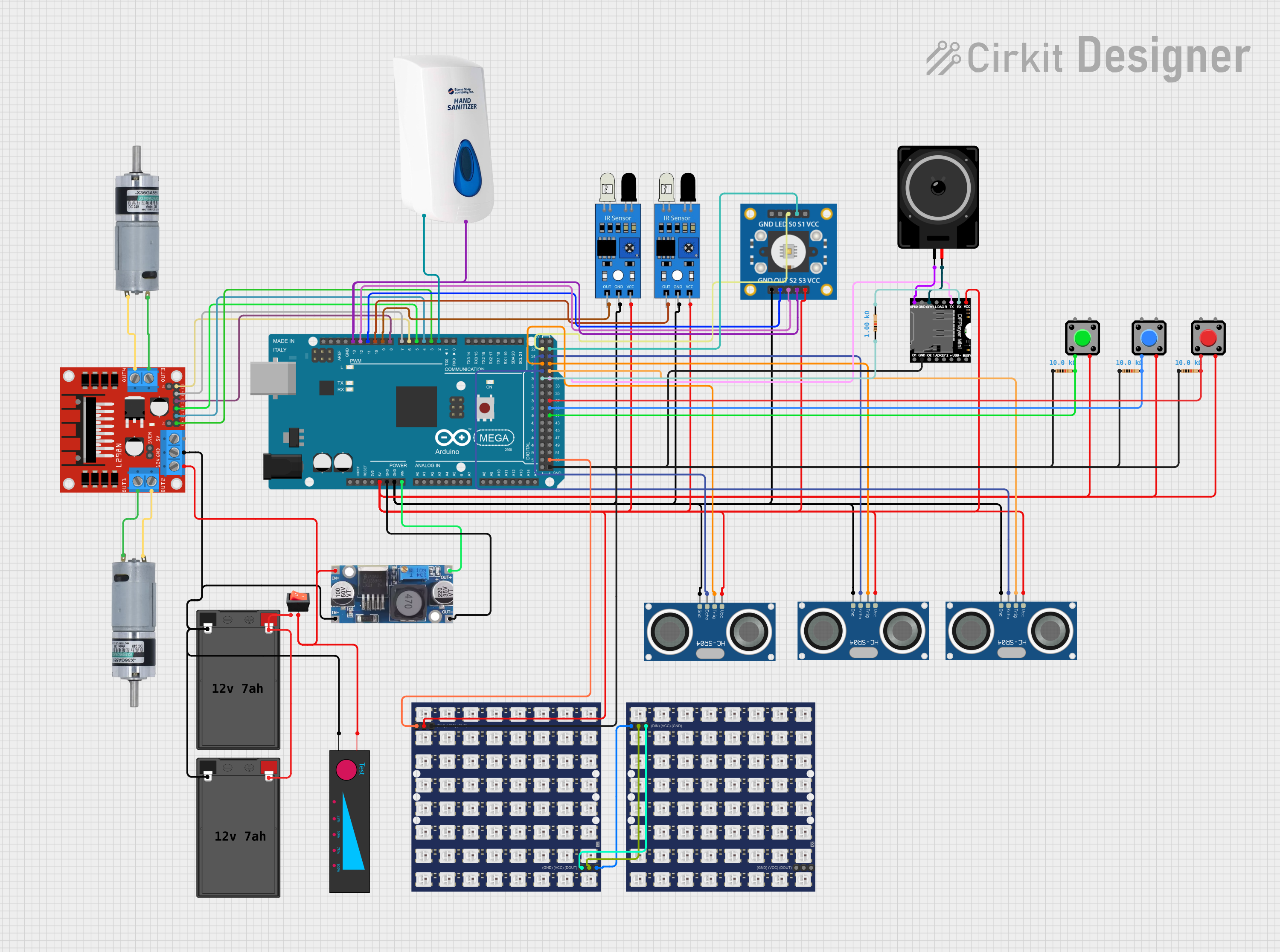
Circuit Documentation
Summary
The circuit design is for a 2-Wheeled Nurse Staff Robot, which is a line-following robot equipped with various sensors and actuators. The robot is designed to respond to button presses, follow lines, detect colors, interact with obstacles, and provide audio feedback. It features an Arduino Mega 2560 as the central microcontroller, infrared sensors for line tracking, ultrasonic sensors for obstacle detection, a color sensor, a motor driver for wheel control, an RGB LED matrix for visual feedback, a speaker for audio output, and pushbuttons for user interaction.
Component List
Microcontroller
- Arduino Mega 2560: A microcontroller board based on the ATmega2560, with numerous digital and analog I/O pins.
Sensors
- IR Sensors: Infrared sensors used for line tracking.
- HC-SR04 Ultrasonic Sensors: Ultrasonic distance sensors for obstacle detection.
- TCS3200 Color Sensor: A sensor for detecting colors.
Actuators
- L298N DC Motor Driver: A motor driver module for controlling the wheels of the robot.
- WS2812 RGB LED Matrix 8x8: An 8x8 matrix of RGB LEDs used as the robot's eyes.
- Loudspeaker: An audio output device for providing feedback.
- Servo Motors: Used for moving parts of the robot, such as a hand or arm.
Power
- 12V 7Ah Battery: The main power source for the robot.
- Step Down Buck Converter: A voltage regulator to step down the voltage for components requiring lower voltages.
Miscellaneous
- Pushbuttons: User interface buttons for controlling the robot.
- Resistors: Various resistors used for pull-up/pull-down and current limiting purposes.
- Rocker Switch: A switch to control the power flow in the circuit.
Wiring Details
Arduino Mega 2560
- 5V and GND pins are used to power the 5V components in the circuit.
- Digital pins (D2 to D13, D22 to D31, D37 to D41, D53) are connected to various sensors, actuators, and buttons for control and feedback.
IR Sensors
- VCC connected to 5V power rail.
- GND connected to ground rail.
- OUT pins connected to digital pins on the Arduino for signal reading.
HC-SR04 Ultrasonic Sensors
- VCC connected to 5V power rail.
- GND connected to ground rail.
- TRIG and ECHO pins connected to digital pins on the Arduino for distance measurement.
TCS3200 Color Sensor
- VCC connected to 5V power rail.
- GND connected to ground rail.
- OUT, S0, S1, S2, S3 pins connected to digital pins on the Arduino for color detection.
L298N DC Motor Driver
- 12V connected to the battery through a rocker switch.
- GND connected to the battery's negative terminal.
- ENA, ENB, IN1, IN2, IN3, IN4 connected to digital pins on the Arduino for motor control.
- OUT1, OUT2, OUT3, OUT4 connected to the motors.
WS2812 RGB LED Matrix 8x8
- VCC connected to 5V power rail.
- GND connected to ground rail.
- DIN connected to a digital pin on the Arduino for LED control.
Loudspeaker
- Connected to the DFPlayer Mini module for audio output.
Pushbuttons
- One side connected to digital pins on the Arduino.
- Other side connected to ground through a resistor for debouncing.
Step Down Buck Converter
- IN+ and IN- connected to the battery.
- OUT+ and OUT- connected to the 5V power rail and ground rail, respectively.
Resistor
- Used in various places for pull-up/pull-down and current limiting purposes.
Rocker Switch
- Connected in series with the battery and the motor driver to control power flow.
Documented Code
The code for the Arduino Mega 2560 is written in C++ and is used to control the robot's behavior. The code is structured into setup and loop functions, with additional functions for specific tasks like moving the motors, detecting colors, and handling button presses.
#include <Servo.h>
#include <Adafruit_NeoPixel.h>
#include <SoftwareSerial.h>

// Pin definitions
// MOTORS
#define LEFT_MOTOR_EN 3
#define LEFT_MOTOR_IN1 4
#define LEFT_MOTOR_IN2 5
#define RIGHT_MOTOR_EN 6
#define RIGHT_MOTOR_IN3 7
#define RIGHT_MOTOR_IN4 8
// IR SENSOR
#define IR_SENSOR_LEFT 9
#define IR_SENSOR_RIGHT 10
// COLOR SENSOR
#define COLOR_SENSOR_OUT 11
#define COLOR_SENSOR_S2 12
#define COLOR_SENSOR_S3 13
#define COLOR_SENSOR_S0 22
#define COLOR_SENSOR_S1 23
// ULTRASONIC SENSOR
#define ULTRASONIC_TRIG1 26
#define ULTRASONIC_ECHO1 24
#define ULTRASONIC_TRIG2 27
#define ULTRASONIC_ECHO2 25
#define ULTRASONIC_TRIG3 29
#define ULTRASONIC_ECHO3 28
// BUTTONS
#define BUTTON_RED 37
#define BUTTON_BLUE 39
#define BUTTON_GREEN 41
// HAND SERVO MOTOR
#define SERVO_LEFT_PIN 2
#define SERVO_RIGHT_PIN 2
// LEDS
#define LED_MATRIX_PIN 53
// SPEAKER
#define SPEAKER_RX 31
#define SPEAKER_TX 30

// Constants
#define LED_MATRIX_NUM_PIXELS 64
#define OBSTACLE_DETECTION_INTERVAL 3000

// Global variables
Servo leftServo;
Servo rightServo;
Adafruit_NeoPixel ledMatrix(LED_MATRIX_NUM_PIXELS, LED_MATRIX_PIN, NEO_GRB + NEO_KHZ800);
SoftwareSerial speaker(SPEAKER_RX, SPEAKER_TX);
unsigned long lastObstacleDetectionTime = 0;

void setup() {
  // Initialize motors, sensors, buttons, servos, LED matrix, and speaker
  // Set pin modes and attach servos
  // Initialize LED matrix and speaker
  // Set initial state: stop motors and blink eyes
}

void loop() {
  // Main loop to handle button presses, line following, color detection,
  // storage check, obstacle detection, and servo movement
}

// Additional functions for moving, stopping motors, detecting color,
// checking storage, detecting obstacles, moving servos, blinking eyes,
// setting eyes color, returning to default position, and turning off the robot
This code snippet provides the structure and constants for the robot's operation. The full implementation of each function would control the robot's motors, read sensor data, and manage the robot's interactions with its environment.