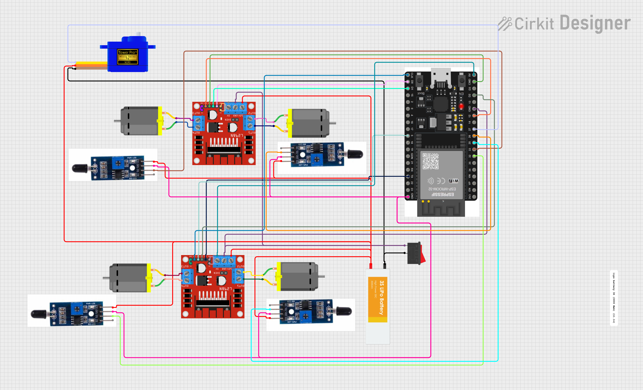
ESP32-Controlled Robot with L298N Motor Drivers and Flame Detection

Circuit Documentation
Summary
This circuit is designed to control a set of DC motors using an L298N DC motor driver, interfaced with an ESP32 microcontroller. The circuit includes servomotors for precise movement control, heat flame sensors for detecting fire or high temperatures, and a Lipo battery for power supply. A rocker switch is used to control the power flow to the circuit. The ESP32 microcontroller is programmed to read inputs from the heat flame sensors and control the motors and servomotor accordingly.
Component List
Lipo Battery
- Description: A rechargeable battery that provides power to the circuit.
- Pins: VCC, GND
Rocker Switch
- Description: A switch to control the power supply to the circuit.
- Pins: 1, 2
L298N DC Motor Driver
- Description: A module to control the direction and speed of DC motors.
- Pins: OUT1, OUT2, 12V, GND, 5V, OUT3, OUT4, 5V-ENA-JMP-I, 5V-ENA-JMP-O, +5V-J1, +5V-J2, ENA, IN1, IN2, IN3, IN4, ENB
Servomotor SG90
- Description: A small and lightweight servomotor for precise control.
- Pins: SIG, VCC, GND
DC Motor
- Description: A motor that converts electrical energy into mechanical energy.
- Pins: pin 1, pin 2
Heat Flame Sensor
- Description: A sensor that detects the presence of a flame or high temperature.
- Pins: AO, DO, GND, VCC
ESP32 38 PINS
- Description: A microcontroller with a wide range of functionalities including Wi-Fi and Bluetooth.
- Pins: GND, 23, 22/SCL, 1, 2, 21/SDA, 19, 18, 5, 17/TX2, 16/RX2, 4, 0, 15, D1, D0, CLK, 3V3, EN, VP, VN, 34, 35, 32, 33, 25, 26, 27, 14, 12, 13, D2, D3, 11, 5V/VIN
Wiring Details
Lipo Battery
- VCC connected to 12V of both L298N DC motor drivers and VCC of all Heat Flame Sensors.
- GND connected to Rocker Switch pin 2 and GND of Servomotor SG90.
Rocker Switch
- Pin 1 connected to GND of L298N DC motor drivers and ESP32 microcontroller.
L298N DC Motor Driver (First Instance)
- OUT1, OUT2 connected to pins of a DC Motor.
- 12V connected to VCC of Lipo Battery.
- GND connected to Rocker Switch pin 1.
- 5V connected to 5V/VIN of ESP32 microcontroller.
- ENA connected to +5V-J1.
- IN1, IN2, IN3, IN4 connected to ESP32 pins D0, D1, 11, 12 respectively.
- ENB connected to +5V-J2.
L298N DC Motor Driver (Second Instance)
- OUT3, OUT4 connected to pins of another DC Motor.
- 12V connected to VCC of Lipo Battery.
- GND connected to Rocker Switch pin 1.
- ENA connected to +5V-J1.
- IN1, IN2, IN3, IN4 connected to ESP32 pins 1, D2, 5, CLK respectively.
- ENB connected to +5V-J2.
Servomotor SG90
- SIG connected to pin 27 of ESP32 microcontroller.
- VCC connected to VCC of Lipo Battery.
- GND connected to GND of Lipo Battery.
DC Motor
- Each DC Motor has two pins connected to OUT1/OUT2 or OUT3/OUT4 of the corresponding L298N DC motor driver.
Heat Flame Sensor
- AO pins are not connected in this circuit.
- DO pins connected to pins 32, 33, 25, 26 of ESP32 microcontroller.
- GND pins connected to GND of ESP32 microcontroller.
- VCC pins connected to VCC of Lipo Battery.
ESP32 38 PINS
- GND connected to GND of Lipo Battery and Rocker Switch pin 1.
- D0, D1, 11, 12 connected to IN1, IN2, IN3, IN4 of the first L298N DC motor driver.
- 1, D2, 5, CLK connected to IN1, IN2, IN3, IN4 of the second L298N DC motor driver.
- 27 connected to SIG of Servomotor SG90.
- 32, 33, 25, 26 connected to DO of Heat Flame Sensors.
- 5V/VIN connected to 5V of the second L298N DC motor driver.
Documented Code
// ESP32 Microcontroller Code
bool forward = 0, backward = 0, right = 0, left = 0;
#include <Servo_ESP32.h>

Servo_ESP32 myservo;
int temp1 = 32;
int temp2 = 33;
int temp3 = 26;
int temp4 = 25;
int a = temp1;
int b = temp2;
int c = temp3;
int d = temp4;
int pos = 0;

void setup()
{
  // directions
  pinMode(7, INPUT);
  pinMode(8, INPUT);
  pinMode(12, INPUT);
  pinMode(11, INPUT);
  // flame sensor pins
  pinMode(a, INPUT);
  pinMode(b, INPUT);
  pinMode(c, INPUT);
  pinMode(d, INPUT);
  myservo.attach(27);
  // Outputs
  pinMode(3, OUTPUT);
  pinMode(5, OUTPUT);
  pinMode(6, OUTPUT);
  pinMode(9, OUTPUT);
  digitalWrite(3, LOW);
  digitalWrite(5, LOW);
  digitalWrite(6, LOW);
  digitalWrite(9, LOW);
}

void loop()
{
  forward = digitalRead(12);
  right = digitalRead(7);
  left = digitalRead(11);
  backward = digitalRead(8);

  digitalWrite(3, LOW);
  digitalWrite(5, LOW);
  digitalWrite(6, LOW);
  digitalWrite(9, LOW);

  if (right == 0)
  {
    digitalWrite(3, HIGH);
  }
  if (forward == 0)
  {
    digitalWrite(3, HIGH);
    digitalWrite(5, HIGH);
  }
  if (left == 0)
  {
    digitalWrite(5, HIGH);
  }
  if (backward == 0)
  {
    digitalWrite(6, HIGH);
    digitalWrite(9, HIGH);
  }

  // Read sensor values
  int a = analogRead(temp1);
  int b = analogRead(temp2);
  int c = analogRead(temp3);
  int d = analogRead(temp4);

  // Determine servo position based on sensor values
  if (a >= b && a >= c && a >= d) {
    pos = 0;
  }
  else if (b >= a && b >= c && b >= d) {
    pos = 90;
  }
  else if (c >= a && c >= b && c >= d) {
    pos = 180;
  }
  else if (d >= a && d >= b && d >= c) {
    pos = 260;
  }
  else {
    pos = 0;
  }
  myservo.write(pos);
}
This code is responsible for reading the inputs from the direction pins and flame sensor pins, controlling the DC motors through the L298N motor drivers, and adjusting the position of the servomotor based on the readings from the flame sensors. The code uses the Servo_ESP32 library to control the servomotor.