
Piezo Sensor-Based Energy Harvesting System with Battery-Powered Bulb and Arduino Monitoring
View and Edit Project In Cirkit Designer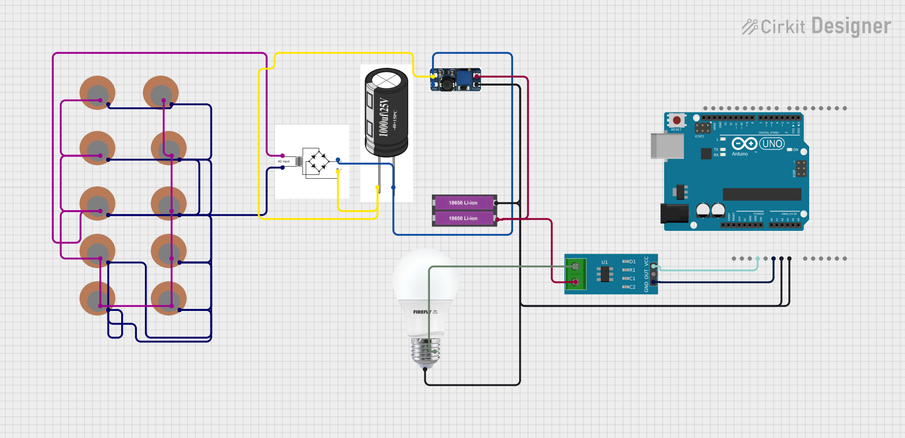
Circuit Documentation
Summary
This circuit is designed to utilize multiple piezo sensors to generate an AC signal, which is then rectified and boosted to power a load (a bulb) and an Arduino UNO microcontroller. The circuit also includes a current sensor to monitor the current flowing through the load.
Component List
Piezo Sensor
- Pins: +, -
- Description: Converts mechanical energy into electrical energy.
1000uF/25V Capacitor
- Pins: +, -
- Description: Stores electrical energy and smooths out voltage fluctuations.
18650 Li-ion Battery x 2
- Pins: +, -
- Description: Provides a stable DC power supply.
Bulb
- Pins: +, -
- Description: Acts as a load to consume electrical power.
Bridge Rectifier
- Pins: AC input +, AC input -, +, -
- Description: Converts AC to DC.
DC-DC Boost Converter
- Pins: VIN-, VIN+, VOUT+, VOUT-
- Description: Boosts the DC voltage to a higher level.
Current Sensor 5A
- Pins: 1, 2, GND, OUT, VCC
- Description: Measures the current flowing through the circuit.
Arduino UNO
- Pins: UNUSED, IOREF, Reset, 3.3V, 5V, GND, Vin, A0, A1, A2, A3, A4, A5, SCL, SDA, AREF, D13, D12, D11, D10, D9, D8, D7, D6, D5, D4, D3, D2, D1, D0
- Description: Microcontroller for processing and control.
Wiring Details
Piezo Sensors
Positive Pins (+)
- Connected to:
- Bridge Rectifier (AC input +)
- Other Piezo Sensors' positive pins
- Connected to:
Negative Pins (-)
- Connected to:
- Bridge Rectifier (AC input -)
- Other Piezo Sensors' negative pins
- Connected to:
1000uF/25V Capacitor
Positive Pin (+)
- Connected to:
- Bridge Rectifier (+)
- DC-DC Boost Converter (VIN+)
- Connected to:
Negative Pin (-)
- Connected to:
- Bridge Rectifier (-)
- DC-DC Boost Converter (VIN-)
- Connected to:
18650 Li-ion Battery x 2
Positive Pin (+)
- Connected to:
- Bulb (+)
- DC-DC Boost Converter (VOUT+)
- Arduino UNO (Vin)
- Connected to:
Negative Pin (-)
- Connected to:
- DC-DC Boost Converter (VOUT-)
- Current Sensor (2)
- Connected to:
Bulb
Positive Pin (+)
- Connected to:
- 18650 Li-ion Battery x 2 (+)
- Connected to:
Negative Pin (-)
- Connected to:
- Current Sensor (1)
- Connected to:
Bridge Rectifier
AC input +
- Connected to:
- Piezo Sensors' positive pins
- Connected to:
AC input -
- Connected to:
- Piezo Sensors' negative pins
- Connected to:
Positive Pin (+)
- Connected to:
- 1000uF/25V Capacitor (+)
- DC-DC Boost Converter (VIN+)
- Connected to:
Negative Pin (-)
- Connected to:
- 1000uF/25V Capacitor (-)
- DC-DC Boost Converter (VIN-)
- Connected to:
DC-DC Boost Converter
VIN+
- Connected to:
- Bridge Rectifier (+)
- 1000uF/25V Capacitor (+)
- Connected to:
VIN-
- Connected to:
- Bridge Rectifier (-)
- 1000uF/25V Capacitor (-)
- Connected to:
VOUT+
- Connected to:
- 18650 Li-ion Battery x 2 (+)
- Arduino UNO (Vin)
- Connected to:
VOUT-
- Connected to:
- 18650 Li-ion Battery x 2 (-)
- Current Sensor (2)
- Connected to:
Current Sensor 5A
Pin 1
- Connected to:
- Bulb (-)
- Connected to:
Pin 2
- Connected to:
- 18650 Li-ion Battery x 2 (-)
- DC-DC Boost Converter (VOUT-)
- Connected to:
GND
- Connected to:
- Arduino UNO (GND)
- Connected to:
VCC
- Connected to:
- Arduino UNO (3.3V)
- Connected to:
Arduino UNO
GND
- Connected to:
- 18650 Li-ion Battery x 2 (+)
- Current Sensor (GND)
- Connected to:
Vin
- Connected to:
- 18650 Li-ion Battery x 2 (+)
- DC-DC Boost Converter (VOUT+)
- Connected to:
3.3V
- Connected to:
- Current Sensor (VCC)
- Connected to:
Documented Code
Arduino UNO Code
void setup() {
  // put your setup code here, to run once:

}

void loop() {
  // put your main code here, to run repeatedly:

}
This code is a basic template for the Arduino UNO. The setup function is used to initialize any settings or configurations, and the loop function contains the main code that runs repeatedly.