
Robot Interface with Pushbutton-Activated LEDs and Power Supply
View and Edit Project In Cirkit Designer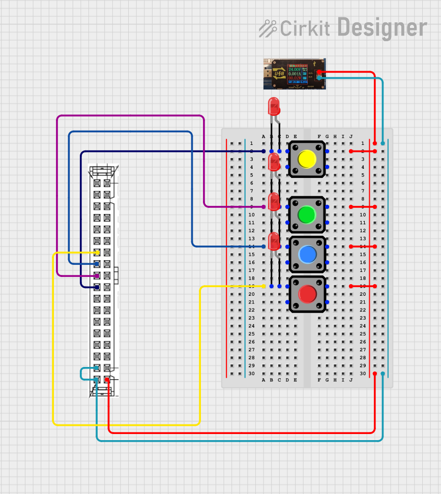
Circuit Documentation
Summary of the Circuit
The circuit in question appears to be a simple control circuit that involves a series of pushbuttons and LEDs. The pushbuttons are used to control the state of the LEDs, likely to turn them on or off. The circuit also includes a RobotConnector, which serves as an interface for external signals or power, and a 24V power supply unit (PSU) to provide the necessary voltage for the circuit operation.
Component List
RobotConnector
- Description: An interface connector for robots, providing a variety of general-purpose input/output (GPIO) pins, power output, and common connections.
- Pins: GPI0-GPI15, 24V_OUT, GPO0-GPO15, OV, COM_Input, NC
24V PSU
- Description: A power supply unit that provides a 24V output.
- Pins: 24V, OV
Pushbutton
- Description: A standard pushbutton used for user input.
- Pins: Pin 1, Pin 2, Pin 3, Pin 4
LED: Two Pin (red)
- Description: A basic two-pin red LED.
- Pins: cathode, anode
Wiring Details
RobotConnector
- GPI9: Connected to the cathode of an LED and Pin 2 of a Pushbutton.
- GPI8: Connected to the cathode of another LED and Pin 2 of a different Pushbutton.
- GPI7: Connected to the cathode of a third LED and Pin 4 of a Pushbutton.
- GPI6: Connected to the cathode of a fourth LED and Pin 4 of another Pushbutton.
- 24V_OUT: Connected to Pin 3 of multiple Pushbuttons and the 24V pin of the 24V PSU.
- OV: Connected to the OV pin of the 24V PSU and the COM_Input pin.
24V PSU
- 24V: Connected to Pin 3 of multiple Pushbuttons and the 24V_OUT pin of the RobotConnector.
- OV: Connected to the OV and COM_Input pins of the RobotConnector.
Pushbutton
- Pin 1: Connected to Pin 1 of other Pushbuttons.
- Pin 2: Connected to the cathode of an LED and a GPI pin on the RobotConnector.
- Pin 3: Connected to the 24V pin of the 24V PSU and the 24V_OUT pin of the RobotConnector.
- Pin 4: Connected to the cathode of an LED and a GPI pin on the RobotConnector.
LED: Two Pin (red)
- cathode: Connected to a GPI pin on the RobotConnector and Pin 2 or Pin 4 of a Pushbutton.
- anode: Directly connected to the cathode pin, forming a loop.
Documented Code
There is no code provided for any microcontrollers in the circuit. If there were microcontrollers present, this section would include the code along with comments explaining the functionality of the code in relation to the circuit operation.