Cirkit Designer
Your all-in-one circuit design IDE
Home /
Project Documentation
Arduino UNO Based Security System with GPS Tracking and Vibration Detection

Circuit Documentation
Summary
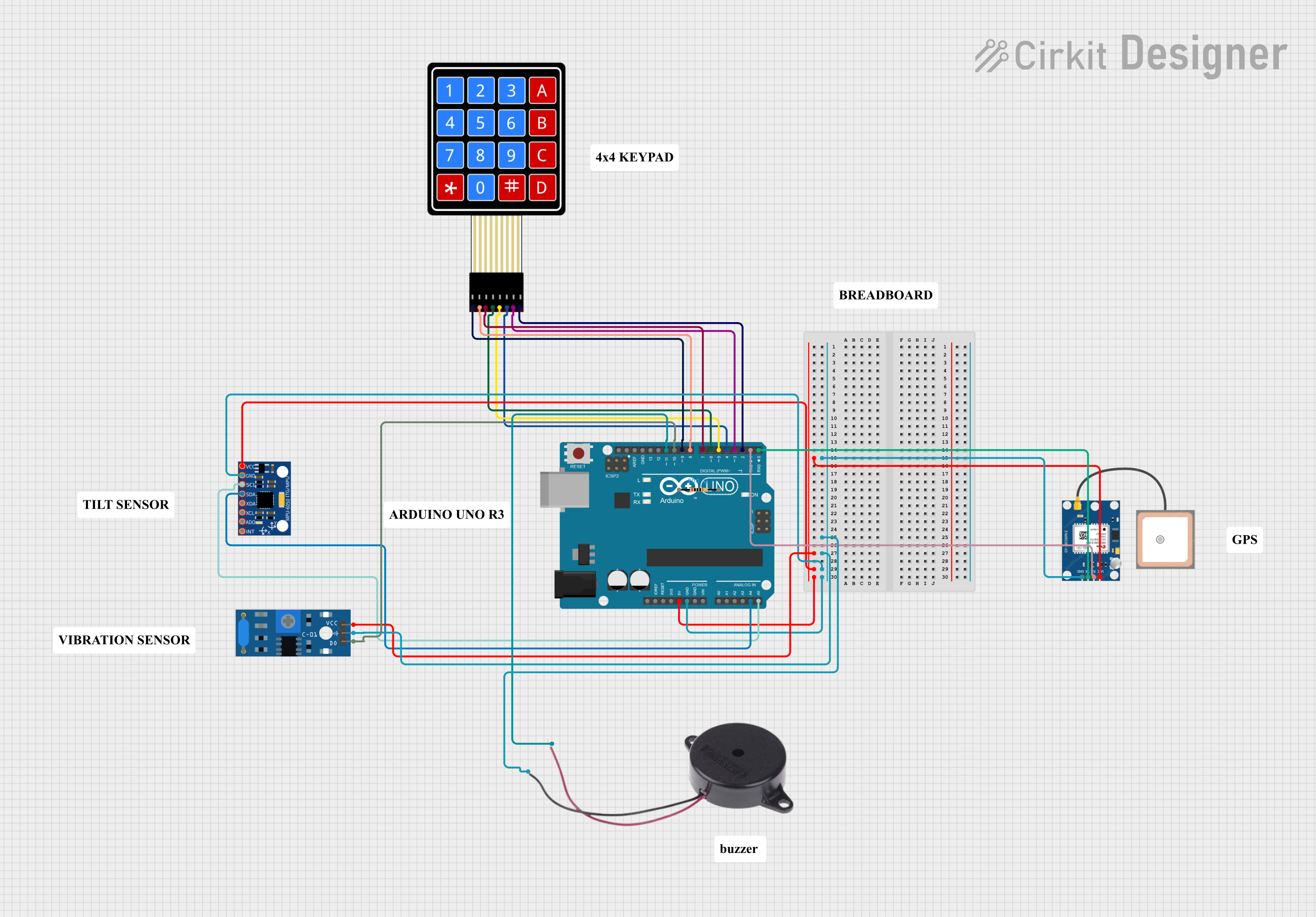
This document provides a detailed overview of a circuit that includes an Arduino UNO as the central microcontroller, interfaced with various sensors and modules including an MPU-6050 motion sensor, a GPS NEO 6M module, an SW-420 vibration sensor, a buzzer, and a 4X4 membrane matrix keypad. The circuit is designed to capture motion data, GPS coordinates, and vibration signals, and provide feedback through a buzzer based on the inputs from these devices.
Component List
Arduino UNO
- Microcontroller board based on the ATmega328P
- It has 14 digital input/output pins, 6 analog inputs, a 16 MHz quartz crystal, a USB connection, a power jack, an ICSP header, and a reset button.
Resistor (200 Ohms)
- A passive two-terminal electrical component that implements electrical resistance as a circuit element.
4X4 Membrane Matrix Keypad
- An input device that provides a grid of buttons for user input.
MPU-6050
- A motion tracking device or IMU (Inertial Measurement Unit) that contains a MEMS accelerometer and a MEMS gyro in a single chip.
SW-420 Vibration Sensor
- A digital vibration sensor that can detect vibrations from various sources.
GPS NEO 6M
- A GPS module that provides location and time information in all weather conditions.
Buzzer
- An audio signaling device that can be mechanical, electromechanical, or piezoelectric.
Wiring Details
Arduino UNO
- 5V connected to MPU-6050 VCC, GPS NEO 6M VCC, and SW-420 Vibration Sensor vcc
- GND connected to MPU-6050 GND, GPS NEO 6M GND, Buzzer NEGATIVE, and SW-420 Vibration Sensor Ground
- A4 (SDA) connected to MPU-6050 SDA
- A5 (SCL) connected to MPU-6050 SCL
- D11 connected to Buzzer POSITIVE
- D10 connected to SW-420 Vibration Sensor Digital output
- D9 - D2 connected to 4X4 Membrane Matrix Keypad R1 to R4 and C1 to C4 respectively
- D1 (TX) connected to GPS NEO 6M RX
- D0 (RX) connected to GPS NEO 6M TX
Resistor (200 Ohms)
- pin1 and pin2 are not connected in the provided net list.
4X4 Membrane Matrix Keypad
- R1 - R4 connected to Arduino UNO D9 to D6 respectively
- C1 - C4 connected to Arduino UNO D5 to D2 respectively
MPU-6050
- VCC connected to Arduino UNO 5V
- GND connected to Arduino UNO GND
- SCL connected to Arduino UNO A5
- SDA connected to Arduino UNO A4
SW-420 Vibration Sensor
- vcc connected to Arduino UNO 5V
- Ground connected to Arduino UNO GND
- Digital output connected to Arduino UNO D10
GPS NEO 6M
- VCC connected to Arduino UNO 5V
- GND connected to Arduino UNO GND
- RX connected to Arduino UNO D1
- TX connected to Arduino UNO D0
Buzzer
- POSITIVE connected to Arduino UNO D11
- NEGATIVE connected to Arduino UNO GND
Documented Code
Arduino UNO Code (sketch.ino)
void setup() {
  // put your setup code here, to run once:

}

void loop() {
  // put your main code here, to run repeatedly:

}
Note: The provided code is a template and does not include any functionality. It needs to be populated with the setup and loop functions to control the components in the circuit.