
Circuit Documentation
Summary of the Circuit
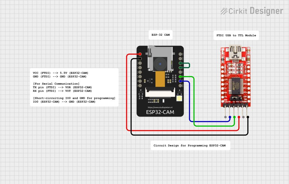
This circuit appears to be designed for programming and communication with an ESP32-CAM module using an FTDI Programmer. The ESP32-CAM is a small camera module with Wi-Fi capabilities that can be used for various IoT applications. The FTDI Programmer is used to upload code to the ESP32-CAM and establish a serial communication interface.
Component List
ESP32 - CAM
- Description: A small-sized camera module with Wi-Fi functionality.
- Pins: 5V, GND, IO12, IO13, IO15, IO14, IO2, IO4, VOT, VOR, VCC, IO0, IO16, 3V3
- Purpose: Acts as the main controller and communication module, capable of capturing images and connecting to the internet.
FTDI Programmer
- Description: A USB to serial converter used to program microcontrollers.
- Pins: DTR, RX, TX, VCC, CTS, GND
- Purpose: Used to upload code to the ESP32-CAM and for serial communication.
Comments
- Description: Placeholder for additional information or notes.
- Pins: None
- Purpose: To provide context or instructions within the circuit design.
Wiring Details
ESP32 - CAM
- 5V connected to FTDI Programmer VCC
- GND connected to FTDI Programmer GND
- VOT (TX of ESP32-CAM) connected to FTDI Programmer RX
- VOR (RX of ESP32-CAM) connected to FTDI Programmer TX
- IO0 connected to GND (commonly used for putting the ESP32-CAM into flashing mode)
FTDI Programmer
- VCC connected to ESP32 - CAM 5V
- GND connected to ESP32 - CAM GND
- RX connected to ESP32 - CAM VOT
- TX connected to ESP32 - CAM VOR
Documented Code
No code has been provided for the microcontrollers in the circuit. Typically, this section would include the source code used for programming the ESP32-CAM, along with comments explaining the functionality of different parts of the code. Since no code is available, this section remains empty. When code is provided, it should be documented here with appropriate explanations and comments for each function and routine.