
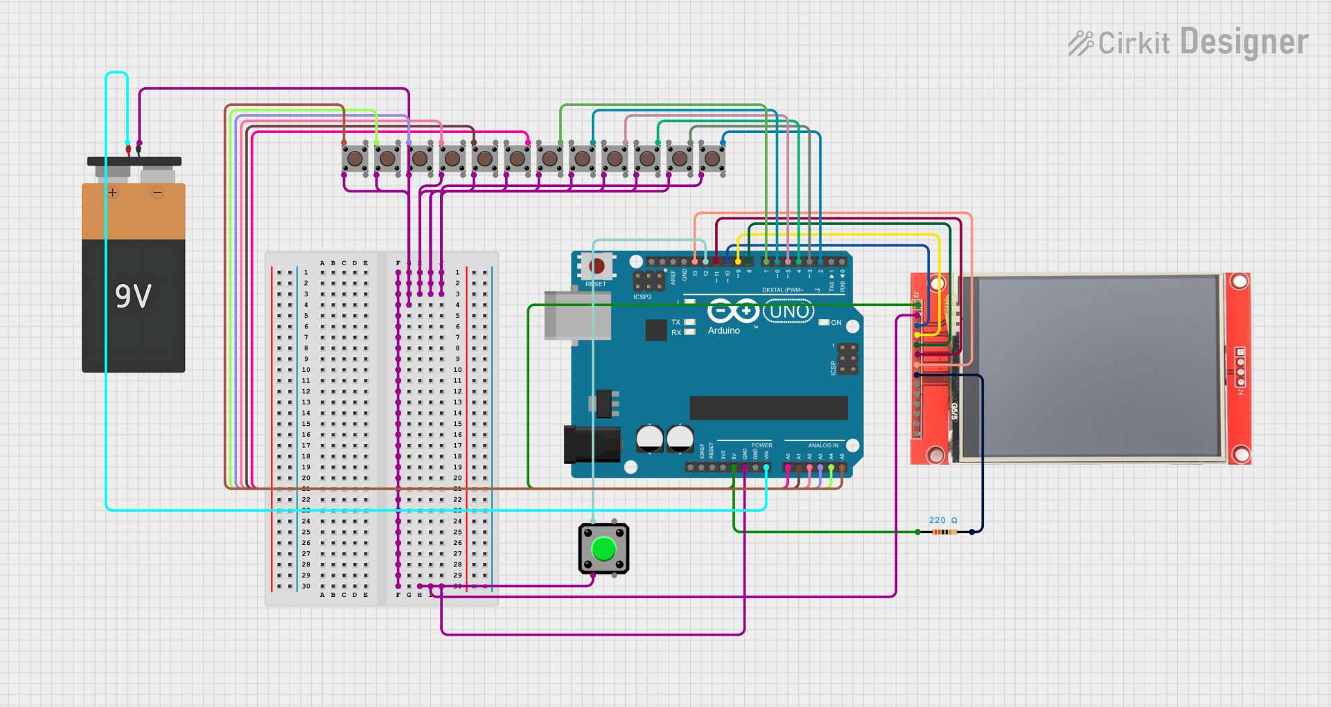
Circuit Documentation
Summary
This circuit is designed to interface an Arduino UNO with an ILI9341 TFT display and multiple pushbuttons. The primary function of the circuit is to create a voting system where each pushbutton corresponds to a candidate, and the votes are displayed on the TFT screen. The Arduino UNO is used as the central processing unit to manage button presses, count votes, and control the display output.
Component List
Arduino UNO
- Microcontroller board based on the ATmega328P
- It has 14 digital input/output pins, 6 analog inputs, a 16 MHz quartz crystal, a USB connection, a power jack, an ICSP header, and a reset button.
ILI9341 TFT Display
- A 240x320 pixel color display with a SPI interface.
- It requires power (VCC), ground (GND), and several data/control lines for operation (CS, RESET, DC/RS, SDI, SCK, LED, SDO, T_CLK, T_CS, T_DIN, T_DO, T_IRQ).
Pushbuttons (12 units)
- Simple tactile switch for user input.
- Each button has four pins: two for the button contacts and two for mechanical stability.
Resistor (220 Ohms)
- A passive two-terminal electrical component that implements electrical resistance as a circuit element.
Battery 9V
- Provides power to the circuit.
Wiring Details
Arduino UNO
- 5V connected to the VCC of the ILI9341 TFT display and one side of the 220 Ohm resistor.
- GND connected to the GND of the ILI9341 TFT display and one side of all pushbuttons.
- Vin connected to the VCC of the 9V Battery.
- A0 - A5 connected to individual pushbuttons.
- D2 - D13 connected to individual pushbuttons and the ILI9341 TFT display.
ILI9341 TFT Display
- VCC connected to the 5V of the Arduino UNO.
- GND connected to the GND of the Arduino UNO.
- CS connected to D10 of the Arduino UNO.
- RESET connected to D9 of the Arduino UNO.
- DC/RS connected to D8 of the Arduino UNO.
- SDI (MOSI) connected to D11 of the Arduino UNO.
- SCK connected to D13 of the Arduino UNO.
- LED connected to the other side of the 220 Ohm resistor.
Pushbuttons
- One side (Pin 2 or Pin 4) of each pushbutton connected to GND of the Arduino UNO.
- The other side (Pin 1 or Pin 3) of each pushbutton connected to individual digital or analog pins on the Arduino UNO (D2 - D7, A0 - A5).
Resistor (220 Ohms)
- One side connected to the 5V of the Arduino UNO.
- The other side connected to the LED pin of the ILI9341 TFT display.
Battery 9V
- VCC connected to the Vin of the Arduino UNO.
- GND connected to the GND of the Arduino UNO.
Documented Code
#include <Adafruit_GFX.h>
#include <Adafruit_ILI9341.h>
#include <SPI.h>

// TFT Display pins
#define TFT_CS     10
#define TFT_RST    9
#define TFT_DC     8

// Create TFT object
Adafruit_ILI9341 tft = Adafruit_ILI9341(TFT_CS, TFT_DC, TFT_RST);

// Pin definitions for buttons
const int masterButton = 12;  // Master Unit Button on Pin 12
const int voteButtons[12] = {2, 3, 4, 5, 6, 7, A0, A1, A2, A3, A4, A5};  // Voting buttons for 12 candidates

// Candidate names
const char* candidateNames[12] = {
  "Alice", "Bob", "Charlie", "David",
  "Eve", "Frank", "Grace", "Heidi",
  "Ivan", "Judy", "Mallory", "Oscar"
};

// Vote count variables
int voteCounts[12] = {0};  // Store vote counts for each candidate
bool votingActive = false;  // Flag for when voting starts

void setup() {
  // Initialize serial communication for debugging
  Serial.begin(9600);

  // Initialize the TFT display
  tft.begin();
  tft.setRotation(3);  // Set rotation to landscape (adjust if needed)
  tft.fillScreen(ILI9341_BLACK);  // Clear the screen

  // Display "Ready for Voting" message
  tft.setCursor(0, 0);
  tft.setTextColor(ILI9341_GREEN);
  tft.setTextSize(2);
  tft.print("Voting Ready!");

  // Set pin modes for buttons with internal pull-up resistors
  pinMode(masterButton, INPUT_PULLUP);  // Master unit button
  for (int i = 0; i < 12; i++) {
    pinMode(voteButtons[i], INPUT_PULLUP);  // Voting buttons
  }
}

void loop() {
  // Check if the Master Unit Button is pressed to start voting
  if (digitalRead(masterButton) == LOW && !votingActive) {
    votingActive = true;
    tft.fillScreen(ILI9341_BLACK);  // Clear the screen
    tft.setCursor(0, 0);
    tft.setTextColor(ILI9341_GREEN);
    tft.setTextSize(2);
    tft.print("Voting Started");
    delay(1000);  // Pause for effect
    updateVoteDisplay();
  }

  // If voting is active, check for votes
  if (votingActive) {
    for (int i = 0; i < 12; i++) {
      if (digitalRead(voteButtons[i]) == LOW) {
        voteCounts[i]++;  // Increment the vote count for the candidate
        Serial.print(candidateNames[i]);
        Serial.println(" received a vote!");
        updateVoteDisplay();  // Update the display with new vote counts
        delay(500);  // Simple debounce delay
      }
    }
  }
}

// Function to update the vote count display
void updateVoteDisplay() {
  tft.fillScreen(ILI9341_BLACK);  // Clear the screen
  tft.setTextColor(ILI9341_WHITE);
  tft.setTextSize(2);

  // Display votes for each candidate in rows
  int yPosition = 0;
  for (int i = 0; i < 12; i++) {
    tft.setCursor(0, yPosition);
    tft.print(candidateNames[i]);
    tft.print(": ");
    tft.print(voteCounts[i]);

    yPosition += 20;  // Move to the next line (adjust for spacing)
    if (yPosition > 220) {
      tft.fillScreen(ILI9341_BLACK);  // Clear screen when it overflows
      yPosition = 0;
    }
  }
}
This code is designed to run on the Arduino UNO and interfaces with the ILI9341 TFT display to create a voting system. It initializes the display and sets up the buttons with internal pull-up resistors. When the master button is pressed, it activates the voting system, and each button press on the voting buttons increments the vote count for the corresponding candidate. The display is updated in real-time to show the current vote counts.