
Arduino UNO Line Follower Robot Car with IR Sensors and Ultrasonic Sensor
View and Edit Project In Cirkit Designer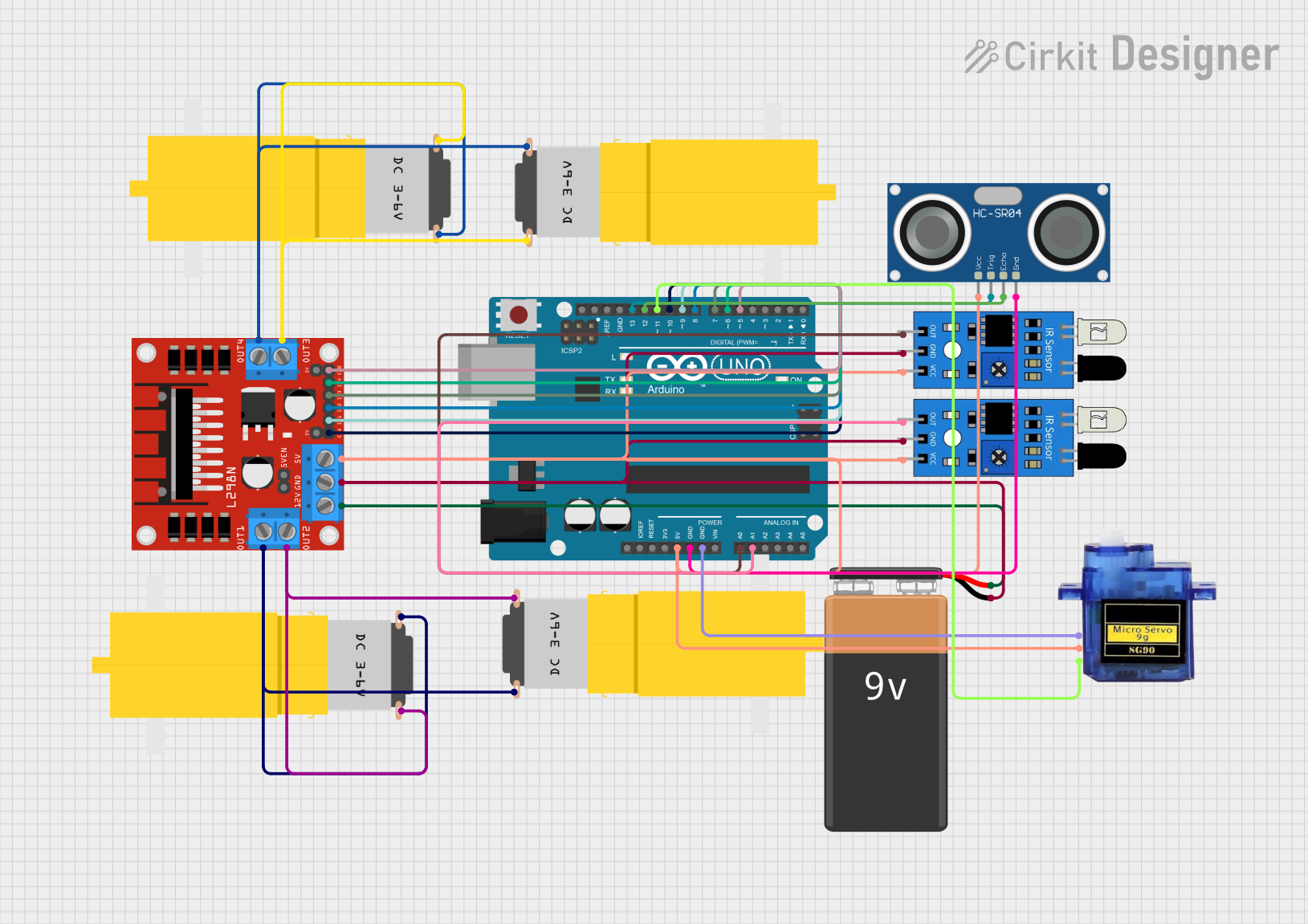
Circuit Documentation
Summary
This document provides a detailed overview of a line follower robot car circuit. The circuit is built using an Arduino UNO microcontroller, an L298N DC motor driver, multiple hobby motors, IR sensors, an ultrasonic sensor, a micro servo, and a 9V battery. The Arduino UNO is programmed to control the motors based on sensor inputs to follow a line.
Component List
Arduino UNO
- Description: A microcontroller board based on the ATmega328P.
- Pins: UNUSED, IOREF, Reset, 3.3V, 5V, GND, Vin, A0, A1, A2, A3, A4, A5, SCL, SDA, AREF, D13, D12, D11, D10, D9, D8, D7, D6, D5, D4, D3, D2, D1, D0
L298N DC Motor Driver
- Description: A dual H-Bridge motor driver module.
- Pins: OUT1, OUT2, 12V, GND, 5V, OUT3, OUT4, 5V-ENA-JMP-I, 5V-ENA-JMP-O, +5V-J1, +5V-J2, ENA, IN1, IN2, IN3, IN4, ENB
Motor amarillo motorreductor hobby
- Description: A small DC motor with a gearbox.
- Pins: vcc, GND
9V Battery
- Description: A standard 9V battery for power supply.
- Pins: -, +
IR Sensor
- Description: An infrared sensor for detecting lines.
- Pins: out, gnd, vcc
HC-SR04 Ultrasonic Sensor
- Description: An ultrasonic sensor for distance measurement.
- Pins: VCC, TRIG, ECHO, GND
Micro Servo 9G
- Description: A small servo motor for precise control.
- Pins: GND, +5V, PWM
Wiring Details
Arduino UNO
- 5V: Connected to +5V of Micro Servo 9G, vcc of IR Sensor (2x), 5V of L298N DC Motor Driver, VCC of HC-SR04 Ultrasonic Sensor
- GND: Connected to GND of HC-SR04 Ultrasonic Sensor, GND of Micro Servo 9G
- A0: Connected to out of IR Sensor
- A1: Connected to out of IR Sensor
- D13: Connected to TRIG of HC-SR04 Ultrasonic Sensor
- D12: Connected to ECHO of HC-SR04 Ultrasonic Sensor
- D11: Connected to PWM of Micro Servo 9G
- D10: Connected to ENA of L298N DC Motor Driver
- D9: Connected to IN1 of L298N DC Motor Driver
- D8: Connected to IN2 of L298N DC Motor Driver
- D7: Connected to IN3 of L298N DC Motor Driver
- D6: Connected to IN4 of L298N DC Motor Driver
- D5: Connected to ENB of L298N DC Motor Driver
L298N DC Motor Driver
- 5V: Connected to 5V of Arduino UNO
- GND: Connected to - of 9V Battery, gnd of IR Sensor (2x)
- 12V: Connected to + of 9V Battery
- OUT1: Connected to GND of Motor amarillo motorreductor hobby (2x)
- OUT2: Connected to vcc of Motor amarillo motorreductor hobby (2x)
- OUT3: Connected to GND of Motor amarillo motorreductor hobby (2x)
- OUT4: Connected to vcc of Motor amarillo motorreductor hobby (2x)
- ENA: Connected to D10 of Arduino UNO
- IN1: Connected to D9 of Arduino UNO
- IN2: Connected to D8 of Arduino UNO
- IN3: Connected to D7 of Arduino UNO
- IN4: Connected to D6 of Arduino UNO
- ENB: Connected to D5 of Arduino UNO
Motor amarillo motorreductor hobby
- GND: Connected to OUT1 of L298N DC Motor Driver (2x), OUT3 of L298N DC Motor Driver (2x)
- vcc: Connected to OUT2 of L298N DC Motor Driver (2x), OUT4 of L298N DC Motor Driver (2x)
9V Battery
- +: Connected to 12V of L298N DC Motor Driver
- -: Connected to GND of L298N DC Motor Driver, gnd of IR Sensor (2x)
IR Sensor
- out: Connected to A0 of Arduino UNO, A1 of Arduino UNO
- gnd: Connected to - of 9V Battery, GND of L298N DC Motor Driver
- vcc: Connected to 5V of Arduino UNO
HC-SR04 Ultrasonic Sensor
- VCC: Connected to 5V of Arduino UNO
- TRIG: Connected to D13 of Arduino UNO
- ECHO: Connected to D12 of Arduino UNO
- GND: Connected to GND of Arduino UNO
Micro Servo 9G
- GND: Connected to GND of Arduino UNO
- +5V: Connected to 5V of Arduino UNO
- PWM: Connected to D11 of Arduino UNO
Code Documentation
/*
Code Name: Arduino Line Follower Robot Car
Code URI: https://circuitbest.com/category/arduino-projects/
Author: Make DIY
Author URI: https://circuitbest.com/author/admin/
Description: This program is used to make Arduino Line Follower Robot Car.
Note: You can use any value between 0 to 255 for M1_Speed, M2_Speed, LeftRotationSpeed, RightRotationSpeed.
Here 0 means Low Speed and 255 is for High Speed.
Version: 1.0
License: Remixing or Changing this Thing is allowed. Commercial use is not allowed.
*/

#define in1 9
#define in2 8
#define in3 7
#define in4 6
#define enA 10
#define enB 5

int M1_Speed = 80; // speed of motor 1
int M2_Speed = 80; // speed of motor 2
int LeftRotationSpeed = 250;  // Left Rotation Speed
int RightRotationSpeed = 250; // Right Rotation Speed

void setup() {
  pinMode(in1, OUTPUT);
  pinMode(in2, OUTPUT);
  pinMode(in3, OUTPUT);
  pinMode(in4, OUTPUT);
  pinMode(enA, OUTPUT);
  pinMode(enB, OUTPUT);
  pinMode(A0, INPUT); // initialize Left sensor as an input
  pinMode(A1, INPUT); // initialize Right sensor as an input
}

void loop() {
  int LEFT_SENSOR = digitalRead(A0);
  int RIGHT_SENSOR = digitalRead(A1);

  if (RIGHT_SENSOR == 0 && LEFT_SENSOR == 0) {
    forward(); // FORWARD
  } else if (RIGHT_SENSOR == 0 && LEFT_SENSOR == 1) {
    right(); // Move Right
  } else if (RIGHT_SENSOR == 1 && LEFT_SENSOR == 0) {
    left(); // Move Left
  } else if (RIGHT_SENSOR == 1 && LEFT_SENSOR == 1) {
    Stop();  // STOP
  }
}

void forward() {
  digitalWrite(in1, HIGH);
  digitalWrite(in2, LOW);
  digitalWrite(in3, HIGH);
  digitalWrite(in4, LOW);
  analogWrite(enA, M1_Speed);
  analogWrite(enB, M2_Speed);
}

void backward() {
  digitalWrite(in1, LOW);
  digitalWrite(in2, HIGH);
  digitalWrite(in3, LOW);
  digitalWrite(in4, HIGH);
  analogWrite(enA, M1_Speed);
  analogWrite(enB, M2_Speed);
}

void right() {
  digitalWrite(in1, LOW);
  digitalWrite(in2, HIGH);
  digitalWrite(in3, HIGH);
  digitalWrite(in4, LOW);
  analogWrite(enA, LeftRotationSpeed);
  analogWrite(enB, RightRotationSpeed);
}

void left() {
  digitalWrite(in1, HIGH);
  digitalWrite(in2, LOW);
  digitalWrite(in3, LOW);
  digitalWrite(in4, HIGH);
  analogWrite(enA, LeftRotationSpeed);
  analogWrite(enB, RightRotationSpeed);
}

void Stop() {
  digitalWrite(in1, LOW);
  digitalWrite(in2, LOW);
  digitalWrite(in3, LOW);
  digitalWrite(in4, LOW);
}
This code is designed to control the line follower robot car. It reads the input from the IR sensors and