Cirkit Designer
Your all-in-one circuit design IDE
Home /
Project Documentation
Arduino-Controlled Traffic Light with Joystick Interface
Circuit Documentation
Summary
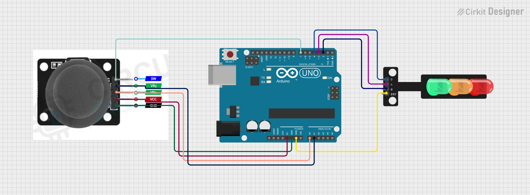
This circuit is designed to control a traffic light module using a joystick module, interfaced with an Arduino UNO microcontroller. The joystick's movements dictate the state of the traffic light LEDs: moving the joystick up turns on the red LED, left for the yellow LED, right for the green LED, and down for all LEDs. The joystick's switch is not used in this application.
Component List
Joystick Module
- Pins: SW, VRY, VRX, VCC, GND
- Description: A module that provides analog input based on its two-axis movement and a digital input from a pushbutton switch.
Arduino UNO
- Pins: UNUSED, IOREF, Reset, 3.3V, 5V, GND, Vin, A0-A5, SCL, SDA, AREF, D0-D13
- Description: A microcontroller board based on the ATmega328P, with digital input/output pins, analog inputs, and various power options.
Traffic Light
- Pins: Green, Yellow, Red, GND
- Description: A module with three LEDs representing a traffic light. Each LED can be controlled individually.
Wiring Details
Joystick Module
- SW (Switch): Not connected.
- VRY (Vertical Axis): Connected to Arduino UNO's A1 (Analog Input 1).
- VRX (Horizontal Axis): Connected to Arduino UNO's A0 (Analog Input 0).
- VCC: Connected to Arduino UNO's 5V.
- GND: Connected to Arduino UNO's GND.
Arduino UNO
- D7: Connected to Joystick Module's SW (not used in this application).
- A1: Connected to Joystick Module's VRY.
- A0: Connected to Joystick Module's VRX.
- 5V: Provides power to Joystick Module.
- GND: Common ground for Joystick Module and Traffic Light.
- D4: Connected to Traffic Light's Green LED.
- D3: Connected to Traffic Light's Yellow LED.
- D2: Connected to Traffic Light's Red LED.
Traffic Light
- Green LED: Controlled by Arduino UNO's D4.
- Yellow LED: Controlled by Arduino UNO's D3.
- Red LED: Controlled by Arduino UNO's D2.
- GND: Connected to Arduino UNO's GND.
Documented Code
/*
 * This Arduino sketch controls a traffic light module using a joystick module.
 * When the joystick is moved up, the red LED turns on.
 * When the joystick is moved left, the yellow LED turns on.
 * When the joystick is moved right, the green LED turns on.
 * When the joystick is moved down, all LEDs turn on.
 */

const int redLED = 2;
const int yellowLED = 3;
const int greenLED = 4;
const int joystickVRX = A0;
const int joystickVRY = A1;
const int joystickSW = 7;

void setup() {
  pinMode(redLED, OUTPUT);
  pinMode(yellowLED, OUTPUT);
  pinMode(greenLED, OUTPUT);
  pinMode(joystickSW, INPUT_PULLUP);
  Serial.begin(9600);
}

void loop() {
  int xValue = analogRead(joystickVRX);
  int yValue = analogRead(joystickVRY);
  int swValue = digitalRead(joystickSW);

  // Joystick up
  if (yValue < 300) {
    digitalWrite(redLED, HIGH);
    digitalWrite(yellowLED, LOW);
    digitalWrite(greenLED, LOW);
  }
  // Joystick left
  else if (xValue < 300) {
    digitalWrite(redLED, LOW);
    digitalWrite(yellowLED, HIGH);
    digitalWrite(greenLED, LOW);
  }
  // Joystick right
  else if (xValue > 700) {
    digitalWrite(redLED, LOW);
    digitalWrite(yellowLED, LOW);
    digitalWrite(greenLED, HIGH);
  }
  // Joystick down
  else if (yValue > 700) {
    digitalWrite(redLED, HIGH);
    digitalWrite(yellowLED, HIGH);
    digitalWrite(greenLED, HIGH);
  }
  // Joystick center
  else {
    digitalWrite(redLED, LOW);
    digitalWrite(yellowLED, LOW);
    digitalWrite(greenLED, LOW);
  }
  delay(100);
}
The code is structured to continuously read the analog values from the joystick's VRX and VRY pins to determine its position. Depending on the position, the corresponding LED on the traffic light is activated. The joystick's switch (SW) is set up as an input with an internal pull-up resistor but is not used in the current logic.