
Arduino-Controlled Multi-Servo System with Potentiometer Feedback
View and Edit Project In Cirkit Designer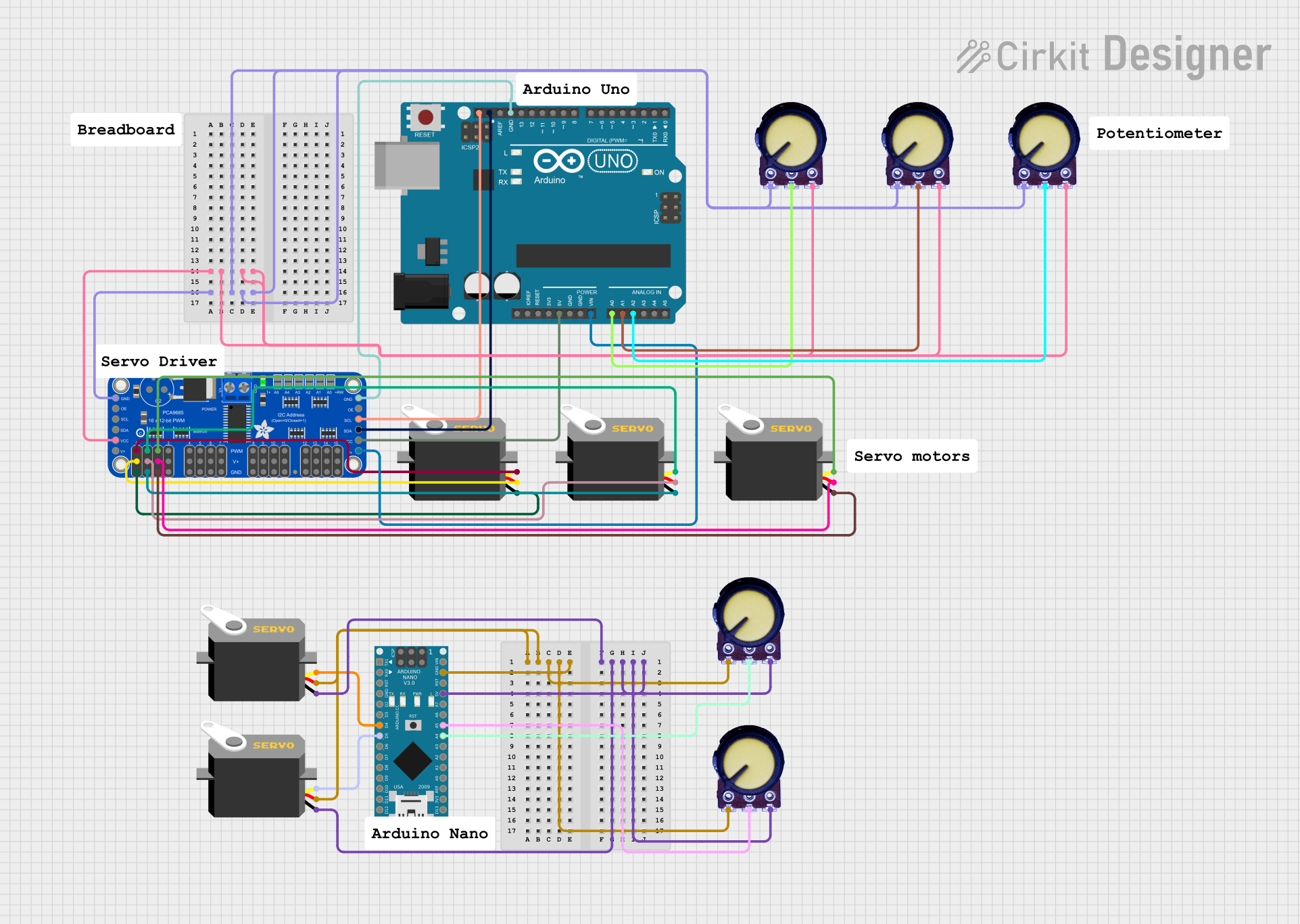
Circuit Documentation
Summary
The circuit in question is designed to control multiple servos using potentiometers as input devices. It consists of an Arduino UNO and an Arduino Nano microcontroller, several potentiometers for input, and servos as output devices. An Adafruit 16-Channel 12-bit PWM Servo Driver is used to extend the number of servos that can be controlled by the Arduino UNO. The servos are powered and controlled through the servo driver, which is interfaced with the Arduino UNO via I2C communication. Additional servos are directly controlled by the Arduino Nano using digital pins.
Component List
Microcontrollers
- Arduino UNO: A microcontroller board based on the ATmega328P, featuring digital and analog I/O pins.
- Arduino Nano: A small, complete, and breadboard-friendly board based on the ATmega328P, similar to the UNO but in a smaller form factor.
Servos
- Servo: An actuator that can be precisely controlled for angular or linear position, speed, and acceleration.
Potentiometers
- Potentiometer: A three-terminal resistor with a rotating or sliding contact that forms an adjustable voltage divider.
PWM Servo Driver
- Adafruit 16-Channel 12-bit PWM Servo Driver - I2C: A board capable of driving up to 16 servos with I2C input from a microcontroller.
Wiring Details
Arduino UNO
- 5V: Powers the Adafruit PWM Servo Driver.
- Vin: Connected to the 5.0V pin of the Adafruit PWM Servo Driver.
- GND: Common ground with the Adafruit PWM Servo Driver.
- A0, A1, A2: Connected to the output of three potentiometers.
- SCL, SDA: I2C communication lines connected to the Adafruit PWM Servo Driver.
Arduino Nano
- 5V: Powers two potentiometers.
- GND: Common ground with two potentiometers and two servos.
- D4, D5: Digital pins connected to the pulse pins of two servos.
- A4, A5: Analog input pins connected to the output of two potentiometers.
Servos
- gnd: Ground connection.
- vcc: Power supply (5V).
- pulse: Control signal input, connected to either the Arduino Nano digital pins or the PWM outputs of the Adafruit PWM Servo Driver.
Potentiometers
- GND: Ground connection.
- Output: Signal output, connected to the analog input pins on the Arduino UNO or Nano.
- VCC: Power supply (5V).
Adafruit 16-Channel 12-bit PWM Servo Driver - I2C
- 5.0V: Power input from the Arduino UNO Vin pin.
- VCC: Logic power supply from the Arduino UNO 5V pin.
- GND: Common ground with the Arduino UNO.
- SDA, SCL: I2C communication lines connected to the Arduino UNO.
- PWM0, PWM1, PWM2: PWM outputs connected to the pulse pins of three servos.
Documented Code
Arduino UNO Code
#include <Wire.h>
#include <Adafruit_PWMServoDriver.h>

// Create a PWM Servo Driver object
Adafruit_PWMServoDriver pwm = Adafruit_PWMServoDriver();

// Servo min and max pulse length out of 4096
int servoMin = 150;  // Min pulse length
int servoMax = 600;  // Max pulse length

// Potentiometer pins
int potPin1 = A0;
int potPin2 = A1;
int potPin3 = A2;

// Servo channels on the servo driver
int servo1 = 0;
int servo2 = 1;
int servo3 = 2;

void setup()
{
  pwm.begin();
  pwm.setPWMFreq(60); // Analog servos run at ~60 Hz
}

void loop()
{
  // Servo 1 controlled by Potentiometer 1
  int potValue1 = analogRead(potPin1);
  int servoPos1 = map(potValue1, 0, 1023, servoMin, servoMax);
  pwm.setPWM(servo1, 0, servoPos1);

  // Servo 2 controlled by Potentiometer 2
  int potValue2 = analogRead(potPin2);
  int servoPos2 = map(potValue2, 0, 1023, servoMin, servoMax);
  pwm.setPWM(servo2, 0, servoPos2);

  // Servo 3 controlled by Potentiometer 3(BASE)
  int potValue3 = analogRead(potPin3);
  int servoPos3 = map(potValue3, 0, 1023, servoMin, servoMax);
  pwm.setPWM(servo3, 0, servoPos3);

  delay(15);  // Small delay for smoother servo movement
}
Arduino Nano Code
#include <Servo.h>

Servo servo1;
Servo servo2;

int potPin1 = A3; // Potentiometer 1 connected to analog pin A0
int potPin2 = A4; // Potentiometer 2 connected to analog pin A1
int potValue1, potValue2;
int servoPos1, servoPos2;

void setup() {
  servo1.attach(3);  // Servo 1 connected to digital pin 9
  servo2.attach(4); // Servo 2 connected to digital pin 10
}

void loop() {
  // Read the potentiometer values
  potValue1 = analogRead(potPin1);
  potValue2 = analogRead(potPin2);

  // Map the potentiometer values to servo angles (0-180 degrees)
  servoPos1 = map(potValue1, 0, 1023, 0, 180);
  servoPos2 = map(potValue2, 0, 1023, 0, 180);

  // Set the servo positions
  servo1.write(servoPos1);
  servo2.write(servoPos2);

  delay(15);  // Small delay to allow the servos to reach their position
}
(Note: The provided code for the Arduino Nano was duplicated, and only one unique code snippet was provided. The documentation section for the Arduino Nano code is based on the unique code snippet.)