
Teensy 4.1 and ESP32 Powered Robotic Controller with CAN Bus and Wireless Communication
View and Edit Project In Cirkit Designer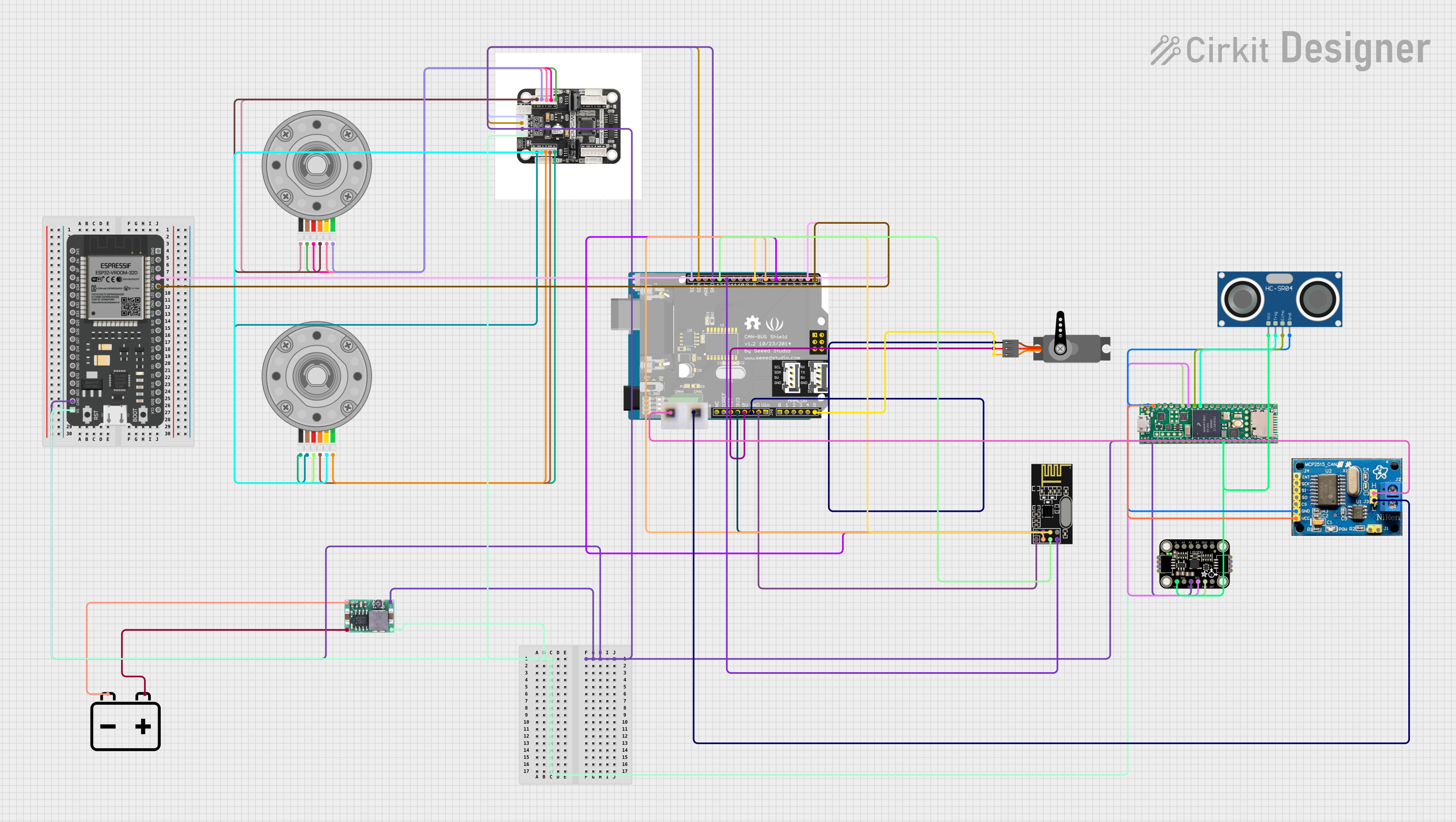
Circuit Documentation
Summary
This document provides a comprehensive overview of a complex circuit that integrates various components including microcontrollers, sensors, a motor driver, a DC-DC converter, a servo, and communication modules. The circuit is designed to perform multiple functions which could include motion control, wireless communication, and environmental sensing. Power is supplied by a 12V battery, regulated to appropriate levels for different components.
Component List
Microcontrollers
- Arduino UNO: A microcontroller board based on the ATmega328P, featuring digital and analog I/O pins.
- ESP32 - 38 pins: A microcontroller with Wi-Fi and Bluetooth capabilities, offering a wide range of GPIO pins.
- Teensy 4.1: A high-performance microcontroller board with extensive I/O capabilities and connectivity options.
Power Supply
- 12v Battery: Provides the primary power source for the circuit.
- Mini-360 DC-DC Step Down Buck Converter: A voltage regulator that steps down the voltage from the battery to a lower level suitable for other components.
Motor Control and Actuators
- 4-Channel Encoder Motor Driver with Onboard Voltage Regulation Circuit: Controls the operation of DC motors with encoder feedback.
- DC Motor with Encoder: A motor that provides rotational movement with encoder feedback for precise control.
- Servo: An actuator capable of precise angular positioning, typically used for steering or control surfaces.
Communication Modules
- NRF24L01: A wireless communication module operating in the 2.4 GHz band, used for short-range communication.
- CAN BUS: A robust vehicle bus standard designed to allow microcontrollers and devices to communicate with each other's applications without a host computer.
- CAN Bus Shield: An interface shield for CAN BUS communication, compatible with microcontroller boards.
Sensors
- HC-SR04 Ultrasonic Sensor: Measures distance by emitting ultrasonic waves and detecting their reflection.
- Adafruit LIS3DH Triple-Axis Accelerometer: A sensor that measures acceleration in three axes.
Miscellaneous
- breadboard-for-can: A simple breakout board for CAN bus connections.
Wiring Details
Arduino UNO
- D7 connected to NRF24L01 MOSI
- D4 connected to NRF24L01 CSN
ESP32 - 38 pins
- 5V connected to 5V net (Mini-360 DC-DC Step Down Buck Converter Output +, 4-Channel Encoder Motor Driver 5V, Teensy 4.1 5V/Input)
- TXD connected to CAN Bus Shield Free
- RXD connected to CAN Bus Shield Free
Teensy 4.1
- 5V/Input connected to 5V net (Mini-360 DC-DC Step Down Buck Converter Output +, 4-Channel Encoder Motor Driver 5V, ESP32 5V)
- Ground connected to GND net (Adafruit LIS3DH Triple-Axis Accelerometer GND, 4-Channel Encoder Motor Driver GND, CAN Bus Shield GND, Mini-360 DC-DC Step Down Buck Converter Output -, ESP32 CMD)
- 3v connected to Adafruit LIS3DH Triple-Axis Accelerometer VCC, HC-SR04 Ultrasonic Sensor VCC
- 19 connected to Adafruit LIS3DH Triple-Axis Accelerometer SDA
- 18 connected to Adafruit LIS3DH Triple-Axis Accelerometer SCL
- 17 connected to HC-SR04 Ultrasonic Sensor ECHO
- 16 connected to HC-SR04 Ultrasonic Sensor TRIG
- 3V connected to CAN BUS VCC
12v Battery
- - connected to Mini-360 DC-DC Step Down Buck Converter Input -
- + connected to Mini-360 DC-DC Step Down Buck Converter Input +
Servo
- VCC connected to CAN Bus Shield 5V
- GND connected to CAN Bus Shield GND
- PWM connected to CAN Bus Shield Free
Mini-360 DC-DC Step Down Buck Converter
- Input - connected to 12v Battery -
- Input + connected to 12v Battery +
- Output + connected to 5V net (4-Channel Encoder Motor Driver 5V, Teensy 4.1 5V/Input, ESP32 5V)
- Output - connected to GND net (Adafruit LIS3DH Triple-Axis Accelerometer GND, 4-Channel Encoder Motor Driver GND, CAN Bus Shield GND, Teensy 4.1 Ground, ESP32 CMD)
4-Channel Encoder Motor Driver with Onboard Voltage Regulation Circuit
- 5V connected to 5V net (Mini-360 DC-DC Step Down Buck Converter Output +, Teensy 4.1 5V/Input, ESP32 5V)
- GND connected to GND net (Adafruit LIS3DH Triple-Axis Accelerometer GND, CAN Bus Shield GND, Mini-360 DC-DC Step Down Buck Converter Output -, ESP32 CMD, Teensy 4.1 Ground)
- SCL connected to CAN Bus Shield SCL
- SDA connected to CAN Bus Shield SDA
- M+ connected to DC Motor with Encoder Motor +ve
- Vcc connected to DC Motor with Encoder VCC
- A connected to DC Motor with Encoder Encoder A
- B connected to DC Motor with Encoder Encoder B
- M- connected to DC Motor with Encoder Motor -ve
DC Motor with Encoder (Two Instances)
- Motor +ve connected to 4-Channel Encoder Motor Driver M+
- VCC connected to 4-Channel Encoder Motor Driver Vcc
- Encoder A connected to 4-Channel Encoder Motor Driver A
- Encoder B connected to 4-Channel Encoder Motor Driver B
- GND connected to 4-Channel Encoder Motor Driver GND
- Motor -ve connected to 4-Channel Encoder Motor Driver M-
NRF24L01
- MOSI connected to Arduino UNO D7
- CSN connected to Arduino UNO D4
- SCK connected to CAN Bus Shield SCK
- MISO connected to CAN Bus Shield MISO
- VCC (3V) connected to CAN Bus Shield 3V3
- GND connected to CAN Bus Shield GND
- CE connected to CAN Bus Shield Free
CAN BUS
- GND connected to HC-SR04 Ultrasonic Sensor GND, Teensy 4.1 Ground
- VCC connected to Teensy 4.1 3V
- H connected to breadboard-for-can H+
- L connected to breadboard-for-can L-
CAN Bus Shield
- GND connected to GND net (Adafruit LIS3DH Triple-Axis Accelerometer GND, 4-Channel Encoder Motor Driver GND, Mini-360 DC-DC Step Down Buck Converter Output -, ESP32 CMD, Teensy 4.1 Ground)
- SCL connected to 4-Channel Encoder Motor Driver SCL
- SDA connected to 4-Channel Encoder Motor Driver SDA
- SCK connected to NRF24L01 SCK
- MISO connected to NRF24L01 MISO
- 3V3 connected to NRF24L01 VCC (3V)
- 5V connected to Servo VCC
- Free connected to Servo PWM, NRF24L01 CE, ESP32 TXD, ESP32 RXD
HC-SR04 Ultrasonic Sensor
- VCC connected to Adafruit LIS3DH Triple-Axis Accelerometer VCC, Teensy 4.1 3v
- GND connected to CAN BUS GND, Teensy 4.1 Ground
- ECHO connected to Teensy 4.1 17
- TRIG connected to Teensy 4.1 16
Adafruit LIS3DH Triple-Axis Accelerometer
- GND connected to GND net (4-Channel Encoder Motor Driver GND, CAN Bus Shield GND, Mini-360 DC-DC Step Down Buck Converter Output -, ESP32 CMD, Teensy 4.1 Ground)
- VCC connected to Teensy 4.1 3v, HC-SR04 Ultrasonic Sensor VCC
- SDA connected to Teensy 4.1 19
- SCL connected to Teensy 4.1 18
breadboard-for-can
- H+ connected to CAN BUS H
- L- connected to CAN BUS L
Documented Code
Arduino UNO Code (sketch.ino)
void setup() {
  // put your setup code here, to run once:

}

void loop() {
  // put your main code here, to run repeatedly:

}
Note: The provided code for the Arduino UNO is a template with empty setup and loop functions. Additional functionality needs to be implemented as per the requirements of the circuit's application.
ESP32 - 38 pins
*No code provided