ESP32-S3 Controlled Pool Monitoring and Management System
Circuit Documentation
Summary
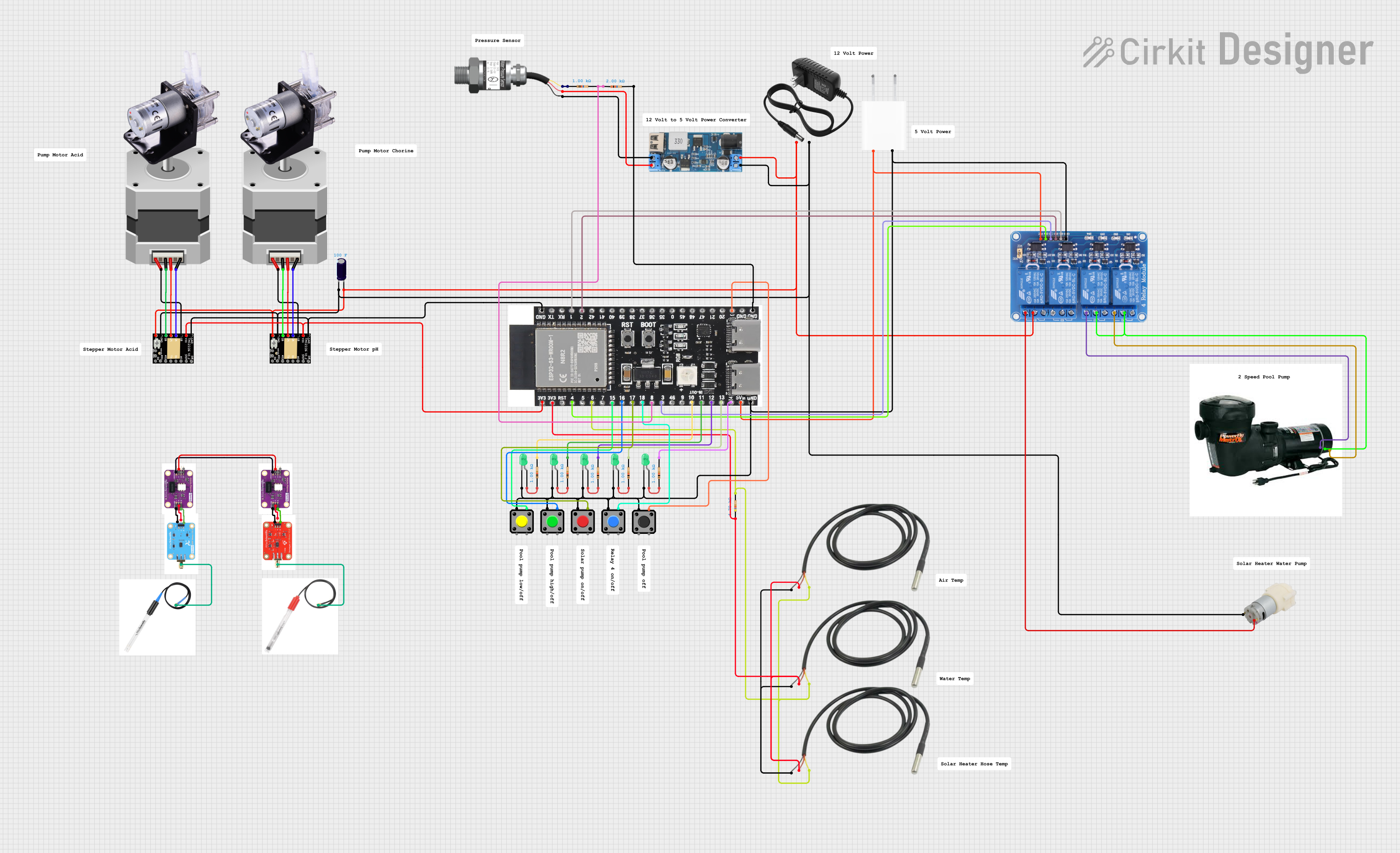
The circuit in question appears to be designed for a pool monitoring and control system. It includes various sensors for temperature and water pressure, actuators such as pumps and a stepper motor, user interface elements like pushbuttons and LEDs, and a microcontroller for logic control. The microcontroller is an ESP32-S3-DevKitC-1-N8R2, which is programmed to interact with the Blynk platform for remote monitoring and control, as well as to manage local inputs and outputs based on sensor data and user input.
Component List
Sensors
- Temperature Sensors: Used to measure temperatures at different points, likely including the pool water, ambient air, and solar heater output.
- Gravity: Analog Water Pressure Sensor: Measures the water pressure, possibly in the pool's plumbing system.
Actuators
- Stepper Motor (Bipolar): Used for precision control of mechanical systems, possibly for valve control or similar applications.
- Peristaltic Pumps: Likely used for dosing chemicals or managing water flow.
- 2 Speed Pool Motor: Controls the pool pump speed, allowing for energy savings or increased flow as needed.
- Water Pump 12V: Used for water circulation or filtration.
User Interface
- Pushbuttons and Red Pushbutton: Allow user interaction, possibly for manual override or control of the system.
- Tactile Switch Buttons - 12mm Square: Provide tactile feedback for user control.
- LEDs (Green): Visual indicators for system status or alerts.
Power Management
- 12V Power Supply: Provides power to the 12V components in the system.
- 5V Adapter: Steps down voltage for 5V components.
- 12V to 5V Step Down Power Converter: Converts 12V to 5V for components requiring lower voltage.
Control and Communication
- ESP32-S3-DevKitC-1-N8R2: The main microcontroller unit that runs the embedded code for controlling the circuit and communicating with the Blynk platform.
- Relay 4 Channel 5v: Allows the microcontroller to control higher power devices such as pumps and motors.
Miscellaneous
- Electrolytic Capacitor: Likely used for power supply smoothing or decoupling.
- Resistors: Used for current limiting or voltage division, essential for protecting LEDs and interfacing with certain sensors.
Wiring Details
Sensors
- Temperature Sensors: Connected to the ESP32 for data acquisition.
- Gravity: Analog Water Pressure Sensor: Signal pin connected to an analog input on the ESP32 through a resistor, VCC connected to a 5V output from a step-down converter, and GND connected to the system ground.
Actuators
- Stepper Motor (Bipolar): Connected to a TMC2226 Stepper Driver, which is in turn controlled by the ESP32.
- Peristaltic Pumps: Likely wired to relays or directly to power, depending on control requirements.
- 2 Speed Pool Motor: Wired to relays for speed control.
- Water Pump 12V: Wired to a relay for on/off control.
User Interface
- Pushbuttons and Red Pushbutton: Wired to the ESP32 for input detection.
- Tactile Switch Buttons - 12mm Square: Wired to the ESP32 for input detection.
- LEDs (Green): Cathodes connected to system ground, anodes connected to ESP32 GPIOs through current-limiting resistors.
Power Management
- 12V Power Supply: Powers the 12V components and is connected to the relays and step-down converter.
- 5V Adapter: Provides 5V power to the ESP32 and other 5V components.
- 12V to 5V Step Down Power Converter: Steps down voltage from the 12V supply to 5V for the ESP32 and other 5V components.
Control and Communication
- ESP32-S3-DevKitC-1-N8R2: Central microcontroller unit, connected to sensors, actuators, user interface elements, and power management components.
- Relay 4 Channel 5v: Controlled by the ESP32 to switch various components on and off.
Miscellaneous
- Electrolytic Capacitor: Wired across the power supply to stabilize voltage.
- Resistors: Wired in series with LEDs and in various places where voltage division or current limiting is necessary.
Documented Code
The embedded code for the ESP32-S3-DevKitC-1-N8R2 microcontroller is written in C++ and designed for the Arduino platform. It includes the following functionalities:
- Blynk Integration: The code integrates with the Blynk platform for remote monitoring and control.
- Temperature Sensing: Utilizes the DallasTemperature library to read temperatures from multiple DS18B20 sensors.
- WiFi Connectivity: Connects to a local WiFi network for internet access and time synchronization.
- Relay Control: Manages four relays for controlling devices such as pumps and motors.
- Button Debouncing: Uses the ezButton library to handle button state changes with debouncing.
- Pressure Sensing: Reads an analog water pressure sensor and calculates the pressure in PSI.
- Scheduled Tasks: Performs certain actions at specific times, such as changing pump speeds or activating a solar heater pump.
- API Integration: Makes HTTP GET requests to an external API for weather data and parses the JSON response.
The code is structured with setup and loop functions, as well as additional functions for handling specific tasks like sensor reading, relay control, and API communication. It uses serial communication for debugging and status messages.
// Code snippet for Blynk integration and relay control
#define BLYNK_TEMPLATE_ID "TMPL2Ew4QXhyB"
#define BLYNK_TEMPLATE_NAME "Pool Monitor"
#define BLYNK_FIRMWARE_VERSION "6.4.4"
#include "BlynkEdgent.h"

#define relayPin1 1  // relay signal pin1
#define relayPin2 2  // relay signal pin2
#define relayPin3 3  // relay signal pin3
#define relayPin4 4  // relay signal pin4

int relay1State = 0;  // Define variable to store relay state
int relay2State = 0;  // Define variable to store relay state
int relay3State = 0;  // Define variable to store relay state
int relay4State = 0;  // Define variable to store relay state

void setup() {
  Serial.begin(115200);
  BlynkEdgent.begin();

  pinMode(relayPin1, OUTPUT);
  pinMode(relayPin2, OUTPUT);
  pinMode(relayPin3, OUTPUT);
  pinMode(relayPin4, OUTPUT);
}

BLYNK_WRITE(V33) {  // Relay Low Setting
  int value = param.asInt();
  if (value == 1) {
    digitalWrite(relayPin1, HIGH);
    relay1State = 1;
  } else {
    digitalWrite(relayPin1, LOW);
    relay1State = 0;
  }
}
The complete code includes additional logic for handling sensor data, user input, and scheduled events. It is designed to be modular and easily expandable for additional features or changes in the circuit design.